Radio controlled boat

a radio controlled and boat technology, applied in the field of radio controlled boats, can solve the problems of not being able to successfully adapt to sea use, prone to topple easily in the waves, and being unable to correct themselves

Inactive Publication Date: 2007-08-02
BARRETT CLIVE VERNON
View PDF4 Cites 11 Cited by
  • Summary
  • Abstract
  • Description
  • Claims
  • Application Information

AI Technical Summary

Benefits of technology

[0014] The float may be bi-coloured, being divided into different-coloured halves parallel to the longitudinal axis of the boat. This enables an observer to tell from a distance in which direction the vessel is traveling.
[0020] A second important feature of the boat is it's ability to submerge or dive under or through approaching waves in the same way that a surfer would push his board an approaching wave to avoid being washed towards the shore.
[0023] In a modification or improvement of this invention, a bow extension element is releasably securable to the bow of the vessel to limit or extend dive capability. In one form, this comprises a similar shape to that of the bow of the vessel and in its simplest form serves to lengthen the bow.
[0026] In an alternative from of the invention in which the vessel may be used as a life-saving apparatus or as a recreational motorized boat, the vessel may be provided with one or more inflatable tubes located about the perimeter of the deck to improve buoyancy. These may be self-inflating. In addition one or more handles may be provided along the length of the deck and / or at the stem to enable persons to grab hold of the vessel and be towed by it.
[0029] For reasons of its use in rough surf and to prevent possible damage to the rudder and / or propeller a propeller and rudder guard is provided.

Problems solved by technology

Whilst bait boats for fresh-water fishing are known, these have not been successfully adapted for use in the sea.
They tend to topple easily in the waves and are unable to right themselves.
As a result they have been found to be ineffective in the sea.
One of the reasons for their inability to remain upright in swells is that prior art bait boats float atop the water and have super-structures, which are acted upon by the waves, resulting in overturning.

Method used


Image

  • Radio controlled boat
  • Radio controlled boat
  • Radio controlled boat

Examples


embodiment of invention

[0030] The preferred embodiments of the invention are described below with reference to the accompanying drawings:

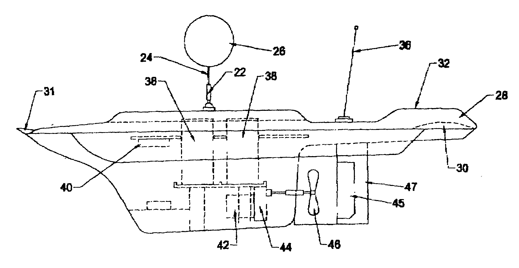
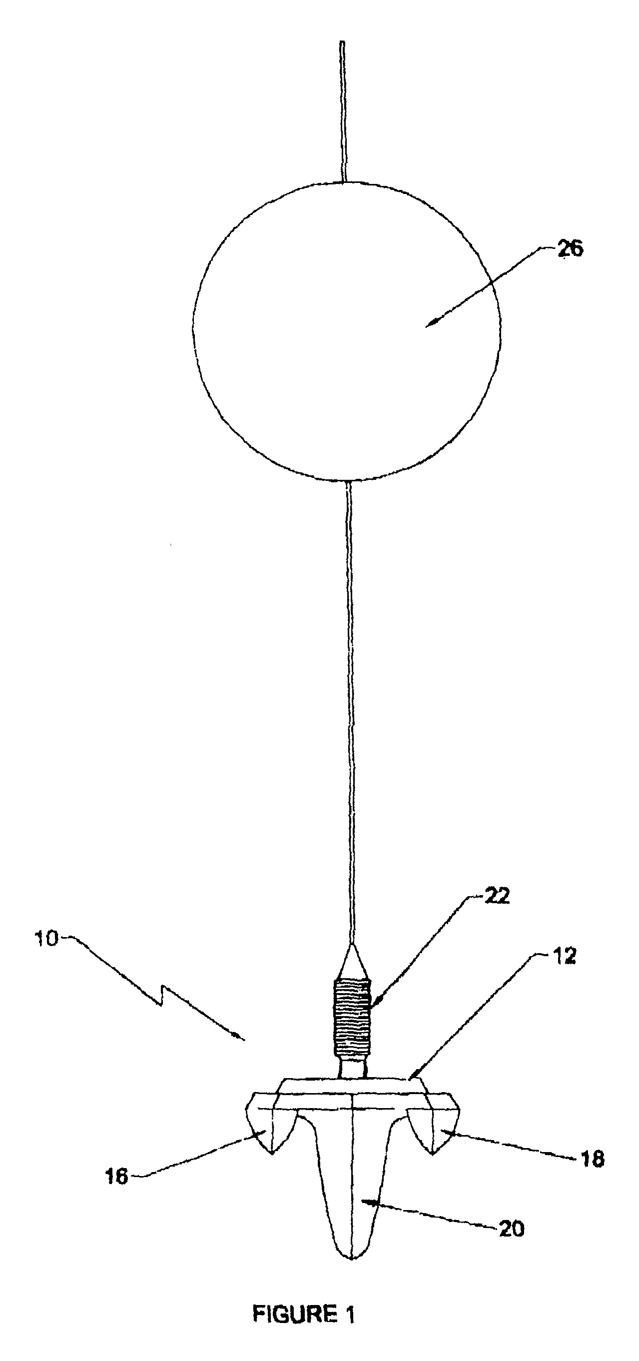
[0031]FIG. 1 is a front view of a boat according to the invention;

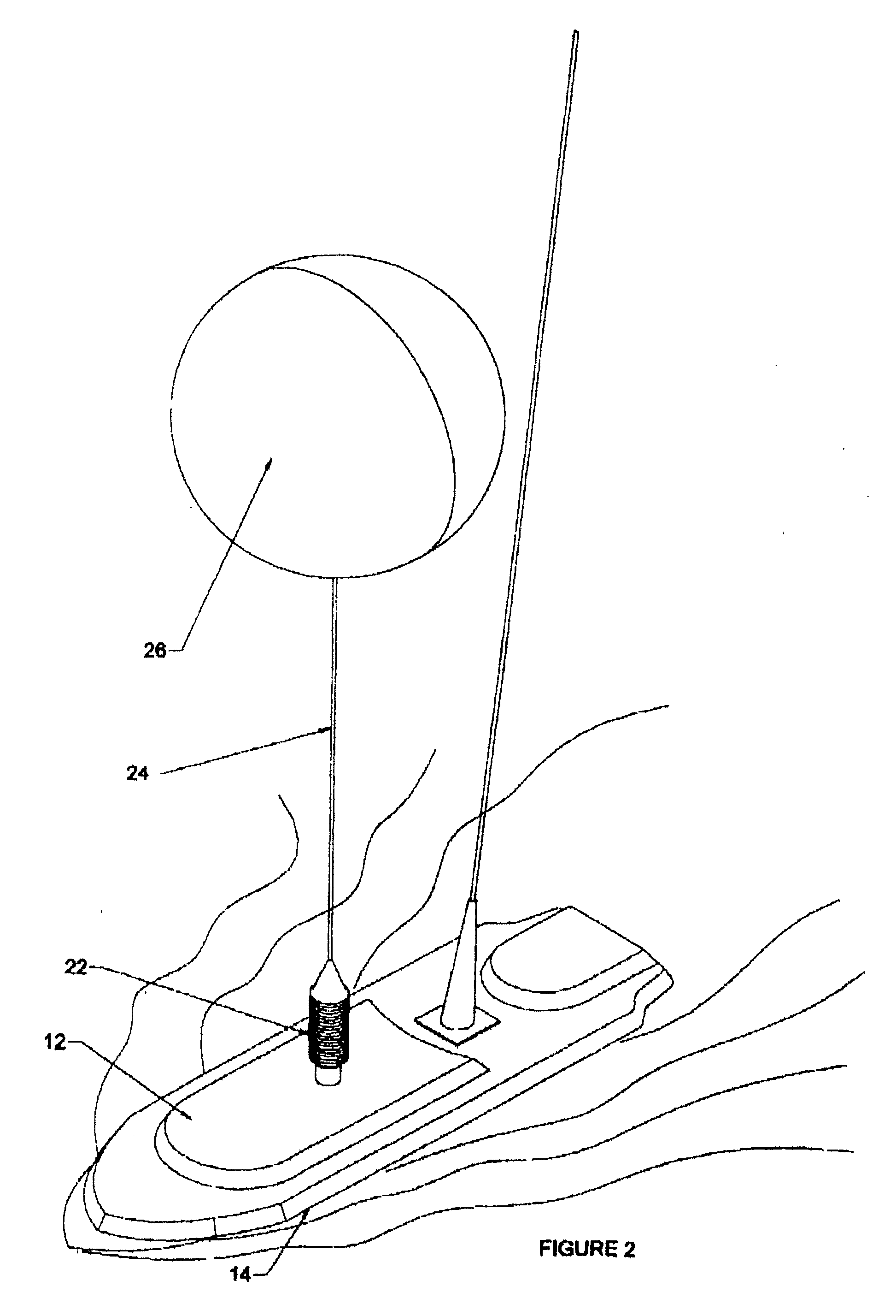
[0032]FIG. 2 is a view of the boat in the water;

[0033]FIG. 3 is a side view of the boat;

[0034]FIG. 4 is a top view of the boat;

[0035]FIG. 5 is a bottom view of the boat;

[0036]FIG. 6 is a front (bow) view;

[0037]FIG. 7 is a rear (stern) view;

[0038]FIGS. 8 and 9 are side and top views of the boat adapted for use in life-saving.

[0039] In FIGS. 1 and 2 a radio controlled bait boat (10) of the invention has a substantially flat deck (12) which is only slightly raised above the water line (14). The boat has twin hulls (16, 18) and a deep and heavy central keel (20). The depth of the keel relative to the exposed height of the deck is approximately in the ratio 5:1 as shown in FIG. 3. This results in an extremely stable vessel.

[0040] The weight of the keel is substantial, with the components of the motor b...


PUM


Abstract

This invention is a surf-launched, a submersible, self-righting radio controlled boat. It is one meter in length, 30 cm wide with a draught of 25 cm. The boat is electrically powered and operates on two 8 amp / hour dry cell batteries which power a 200 watt motor to which a 3:1 ratio reduction gearbox is attached driving a 115 mm 3-blade propeller. It is ideal for delivering a baited fishing line up to one km in oceans, dams and rivers. It is ideally used in conjunction with a battery-operated motorized winch whereby a line from the winch is attached to the boat in addition to the fishing line. Once the fishing line has been released, the winch pulls the boat back to shore. Other applications include underwater photography, recreation or life-saving where the boat itself, fitted with handles becomes a motorized life-buoy or the boat can be used to tow a life-buoy to a drowning bather.

Description

BACKGROUND ART [0001] A bait boat is a radio controlled vessel to which a fishing line and baited hook are attached and carried out to the middle of a lake, for example, where the distance is too great for the fishing hook to be placed by casting. Similarly salt-water anglers may wish to fish beyond the breakers, and again a bait boat would be a desirable means to achieve this. [0002] Whilst bait boats for fresh-water fishing are known, these have not been successfully adapted for use in the sea. They tend to topple easily in the waves and are unable to right themselves. As a result they have been found to be ineffective in the sea. [0003] One of the reasons for their inability to remain upright in swells is that prior art bait boats float atop the water and have super-structures, which are acted upon by the waves, resulting in overturning. [0004] It is therefore an object of this invention to provide a bait boat which lies low in the water, has little or no superstructure, is subme...

Claims


Application Information

Patent Timeline
Patent Type & Authority Applications(United States)
IPC IPC(8): A01K89/00
CPCA01K91/02
Inventor BARRETT, CLIVE VERNON
Owner BARRETT CLIVE VERNON
Why Eureka
Try Eureka