Shearing force reinforced structure and member

a technology of shearing force and reinforcement, applied in mining structures, tunnels, buildings, etc., can solve the problems of inability to use, inconvenient operation, and difficulty in realizing a request for changing the type of shearing preceding failure to a bending preceding failur

Inactive Publication Date: 2007-08-02
KONINKLIJKE PHILIPS ELECTRONICS NV +1
View PDF20 Cites 36 Cited by
  • Summary
  • Abstract
  • Description
  • Claims
  • Application Information

AI Technical Summary

Benefits of technology

[0007] Consequently, the inventor has made a progress of a research and development to cope with the conventional technical problems, and attained to originate the invention. In other words, one aspect of the invention is to provide a shearing force reinforced structure of an existing RC structure body (hereinafter simply referred to as “shearing force reinforced structure”) and a shearing force reinforced member that make it possible to simply and surely ensure a predetermined pulling-out rigidity.

Problems solved by technology

However, in these structures, because a thickness of such a side wall and a bottom slab increases after the reinforcement and an inside space section of a skeleton decreases, there exists a problem that various inconveniences occur (for example, in a case of a water and sewage purification establishment occurs a decrease of a reserving capacity and a processing capacity; in a case of a subway, because a construction limit becomes not satisfied, the subway results in not being usable in some case).
In addition, in the thickness increasing method, because the major reinforcing bar increases, thereby shear force capacity is improved, and on the other hand a bending moment capacity increases, it is difficult to realize a request of changing a shearing preceding failure type to a bending preceding failure.
Furthermore, the thickness increasing method requires a large scale crane in carrying in and building reinforcement members such as a steel plate and a reinforcing bar, and there exists some case that an execution thereof is difficult due to a restriction of the large scale crane in a restricted space such as an inside of an underground structure object and a bridge.
In addition, in a shear force reinforcement inside a road tunnel and a railroad tunnel in common use, there exists some case that an execution is difficult with respect to a request for a rapid execution inside a restricted time zone at night due to a restriction of a traffic amount and train operation thereof.
However, in the reinforcement method, because the predetermined steel plate is merely inserted in the slits, a new problem that a sufficient rigidity (a magnitude of a pulling-out resistance against a pulling-out force, hereinafter referred to as “pulling-out rigidity”) cannot be obtained results in occurring when the pulling-out force is generated in the steel plate.

Method used


Image

  • Shearing force reinforced structure and member
  • Shearing force reinforced structure and member
  • Shearing force reinforced structure and member

Examples


first embodiment

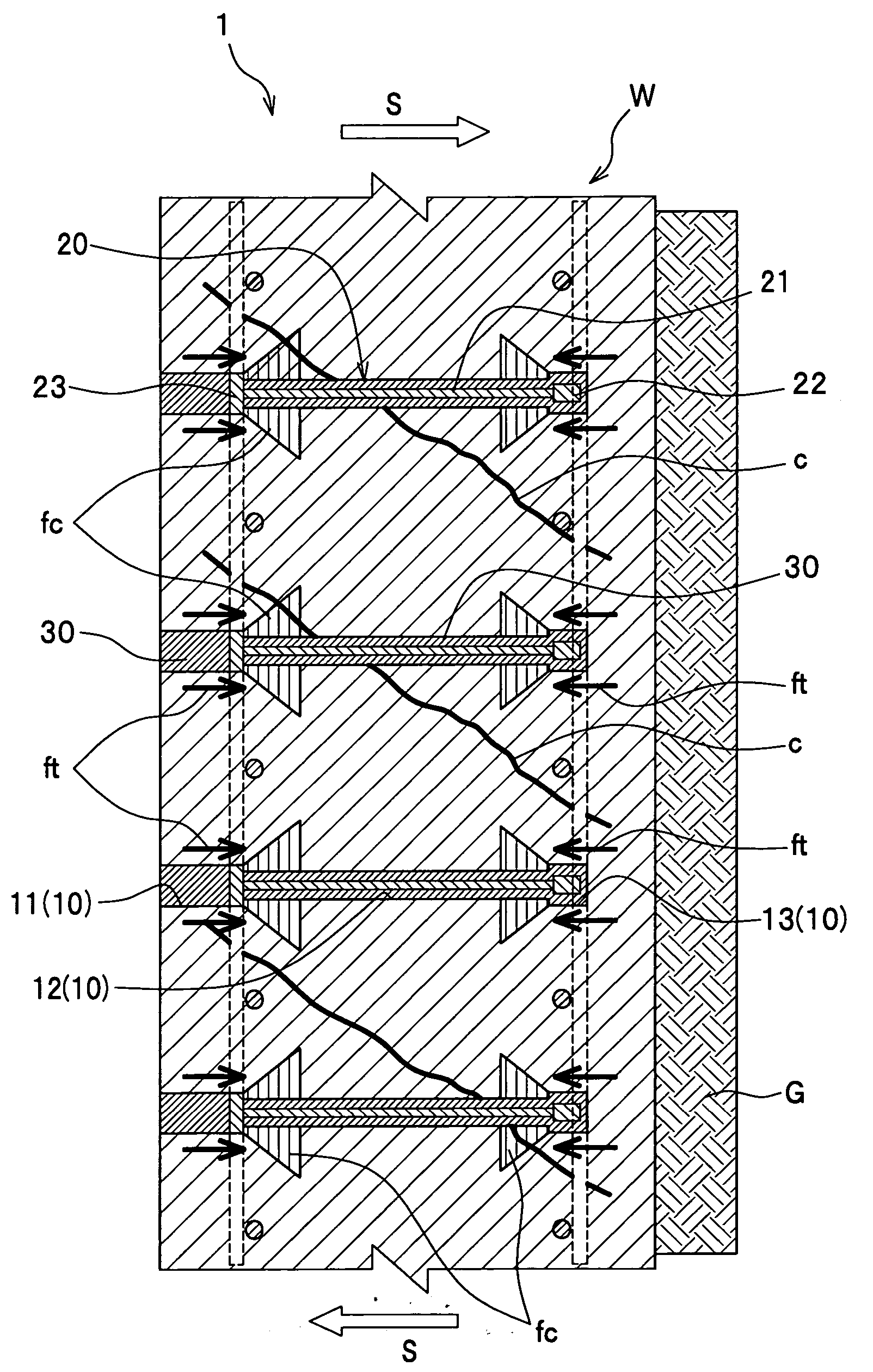
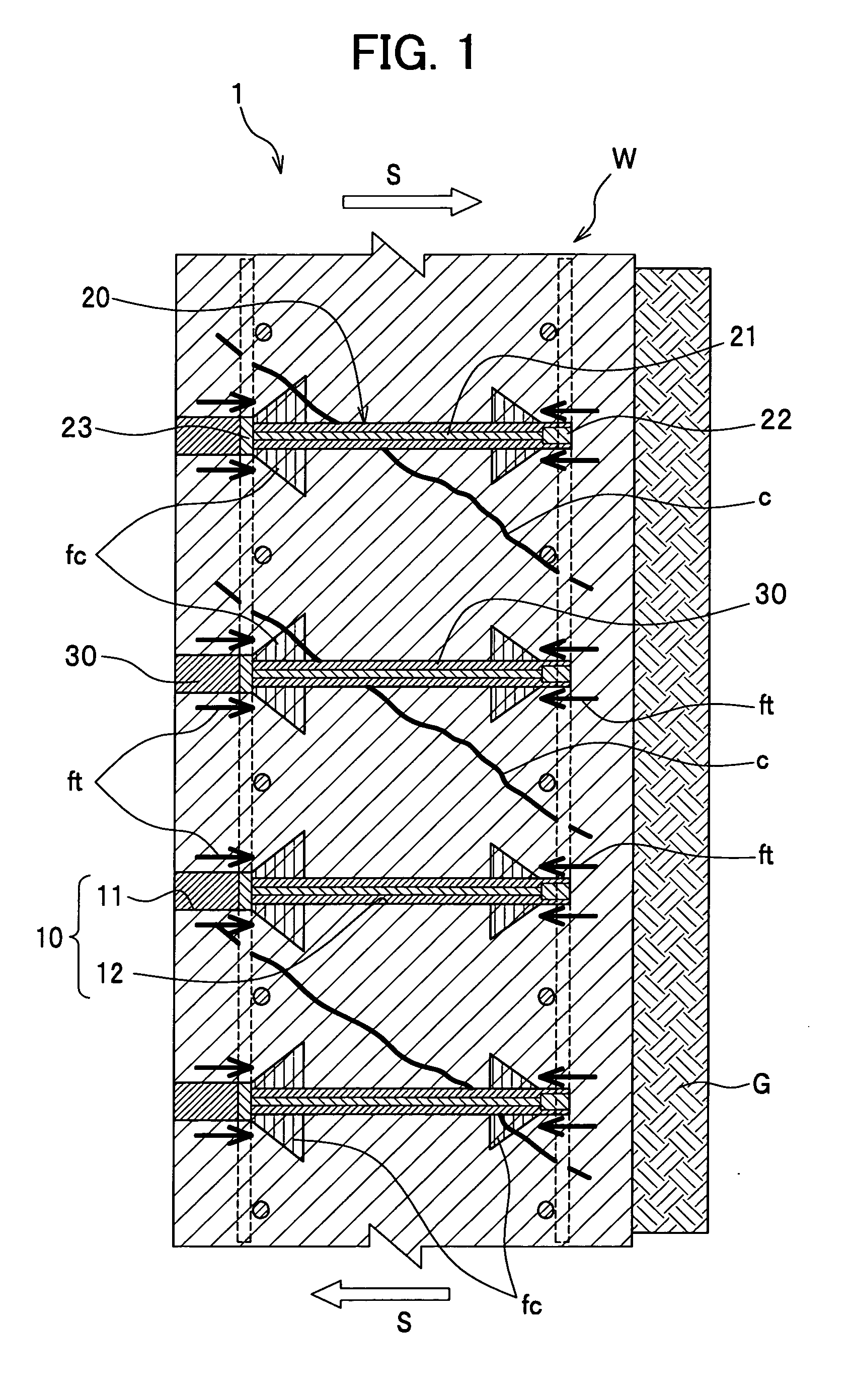
[0074] A shearing force reinforced structure 1 related to a first embodiment of the present invention comprises, as shown in FIG. 1, a side wall W of an existing reinforced concrete structure, shearing force reinforced members 20 respectively arranged inside reinforced member insertion holes 10 with bottoms formed in a direction intersecting a major reinforcing bar from an inner face side of the side wall W; and fillers 30 respectively filled in the holes 10.

[0075] Here, each of the shearing force reinforced members 20 comprises a shearing force reinforcing bar 21 of a wire rod, a ring head (top end fixation member) 22 fixed at a top end of the reinforcing bar 21, and a plate head (base end fixation member) 23 fixed at a base end of the reinforcing bar 21 (see FIG. 3).

[0076] In addition, each of the reinforced member insertion holes 10 comprises a general part 12 having an inner diameter larger than a reinforcing bar diameter of the shearing force reinforcing bar 21 and an outer d...

second embodiment

[0099] A shearing force reinforced structure 2 related to a second embodiment of the present invention comprises, as shown in FIG. 7, the side wall W of an existing reinforced concrete structure, the shearing force reinforced members 20′ arranged inside the reinforced member insertion holes 10 with bottoms formed in a direction intersecting a major reinforcing bar of the side wall W; and the fillers 30 filled in the holes 10.

[0100] Here, each of the shearing force reinforced members 20′ comprises, as shown in FIG. 8, a shearing force reinforcing bar 21′ of a wire rod, and the plate head (base end fixation member) 23 fixed at the base end of the reinforcing bar 21′.

[0101] In addition, each of the reinforced member insertion holes 10 comprises the general part 12 having an inner diameter larger than a reinforcing bar diameter of the shearing force reinforcing bar 21′ and smaller than a width of the plate head 23; and the base end width broadening part 11 formed at the base end of th...

third embodiment

[0117] A reinforcement method related to the third embodiment mainly comprises (1) a reinforced member insertion hole drilling process, (2) a filler filling process, (3) a reinforcing bar insertion process, and (4) a shearing force reinforced member arrangement process.

[0118] (1) Reinforced Member Insertion Hole Drilling Process

[0119] The process drills a reinforced member insertion hole for placing a shearing force reinforced member that penetrates an intermediate wall of an existing RC structure body.

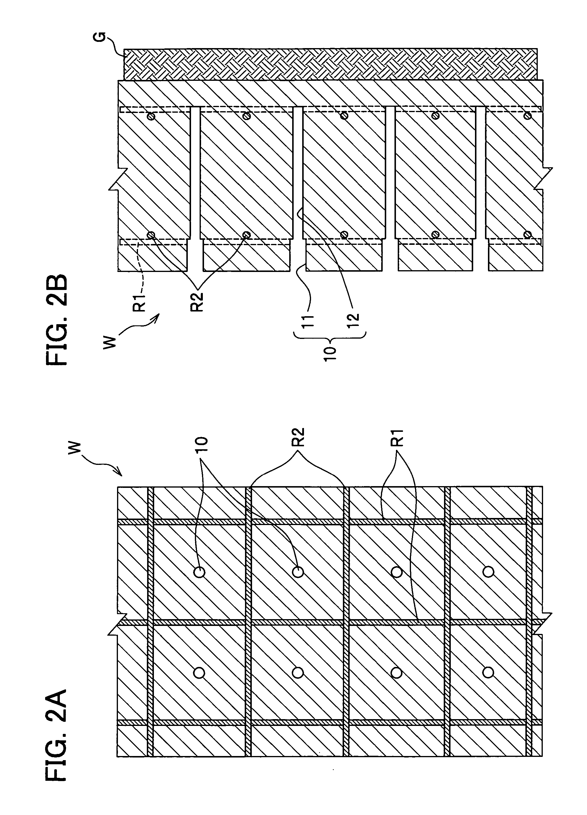
[0120] As shown in FIG. 9A, each of the reinforced member insertion holes 10 is arranged at center of both major reinforcing bars R1 and minor reinforcing bars R2 at a same interval laterally as in the reinforcements R1 and longitudinally as in the reinforcing bars R2 not to damage them in drilling, based on information of a bar arrangement drawing and a nondestructive test in execution of the existing RC structure body. As shown in FIG. 9B, the reinforced member insertion hole 10 ...


PUM


Abstract

The purpose of the present invention is to provide a shearing force reinforced structure of an existing RC structure body that can simply and surely ensure a predetermined pulling-out rigidity. Then a shearing force reinforced structure (1) of the invention is configured with: a side wall (W) of an existing reinforced concrete structure; shearing force reinforced members (20) arranged inside reinforced member insertion holes (10) with bottoms formed in a direction intersecting a major reinforcing bar of the side wall (W); and fillers (30) filled in the holes (10), wherein each of the shearing force reinforced members (20) is configured with a shearing force reinforcing bar (21), a plate head 23 and a ring head (22) respectively fixed at a base end and top end of the reinforcing bar (21); each of the holes (10) is formed at a general part (12) having an inner diameter larger than a reinforcing bar diameter of the reinforcing bar (21) and smaller than a width of the head (23), and a base end width broadening part (11) formed at a base end of the hole 10 and having a diameter larger than the width of the head (23). In accordance with such a shearing force reinforced structure and a shearing force reinforced member, it is enabled to simply and surely ensure a predetermined pulling-out rigidity.

Description

TECHNICAL FIELD [0001] The present invention relates to a shearing force reinforced structure and member (this means “reinforced structure and member for resisting a shearing force”) of a reinforced concrete structure object with respect to a structure object of an existing reinforced concrete (hereinafter a reinforced concrete may be referred to as “RC” in some case) where the shearing force acts. BACKGROUND ART [0002] In various establishments such as a subway and a water and sewerage purifying establishment designed and constructed before the Great Hanshin Earthquake, it is clarified that a reinforced concrete structure object (hereinafter referred to as referred to as “RC structure body” in some case) such as a side wall, bottom slab, intermediate wall, and intermediate slab of a box culvert and underground embedded structure object of an RC structure constituting a structure object skeleton of the various establishments; and a wall type bridge pier is poor in shear force capaci...

Claims


Application Information

Patent Timeline
Patent Type & Authority Applications(United States)
IPC IPC(8): E04C5/08
CPCE04C5/0645E21D11/107E04G23/0218E04C5/16E04G23/02E04C5/01
Inventor TANAKA, YOSHIHIRO
Owner KONINKLIJKE PHILIPS ELECTRONICS NV
Why Eureka
Try Eureka