
Wear indicating tire

Inactive Publication Date: 2007-08-02
MICHELIN & CO CIE GEN DES ESTAB MICHELIN
View PDF4 Cites 35 Cited by
  • Summary
  • Abstract
  • Description
  • Claims
  • Application Information

AI Technical Summary

Benefits of technology

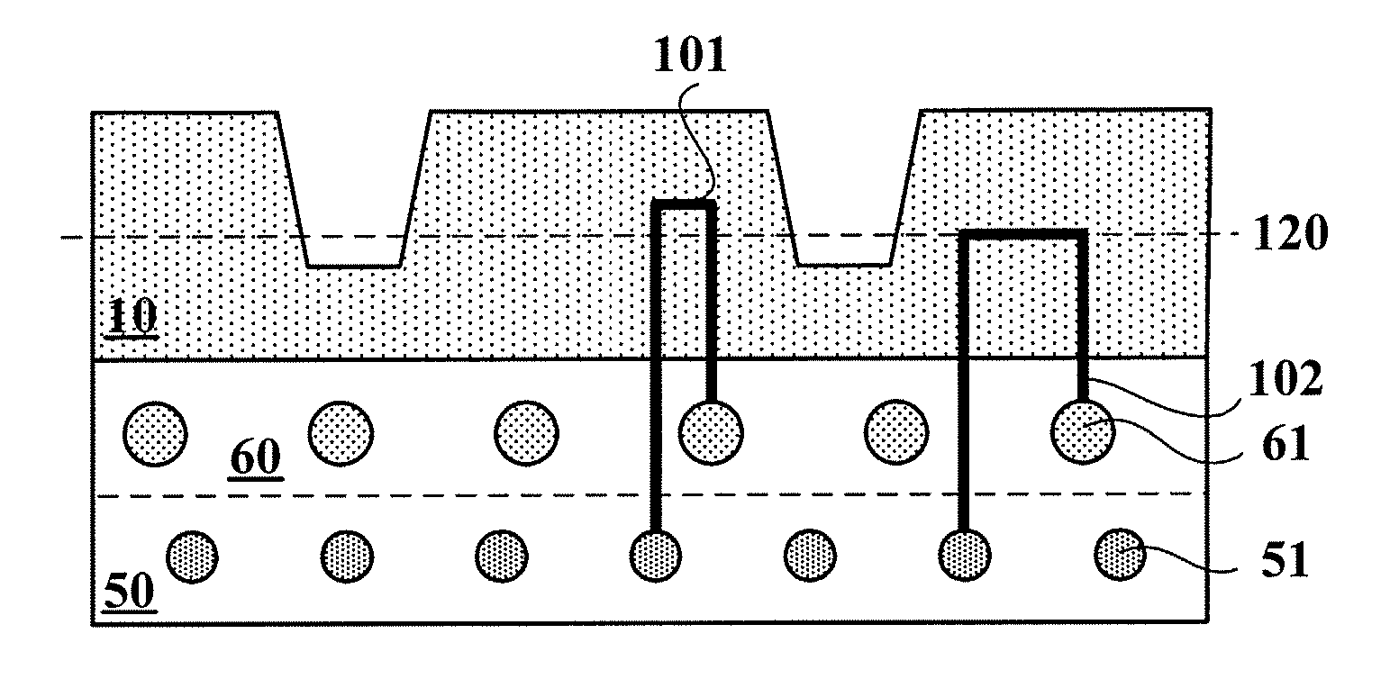
[0017] This goal is achieved by a tire comprising a tread and a belt comprising a first and a second ply, the first and second plies being made up of substantially parallel metallic reinforcing cords embedded in a rubber composition that are inclined with respect to the equatorial plane of the tire, the cords of the first ply being inclined with respect to (and preferentially inclined oppositely to) the cords of the second ply, wherein at least one dipolar electri

Problems solved by technology

As is known, the tread of a tire undergoes wear that results from the rolling of the tire on the ground.
If the tread has grooves, the effect of this wear is to reduce the depth of the grooves, thereby degrading the performance of the tire on wet ground.
On reaching a certain wear level, referred to as “tread wear limit”, the tire no longer enables rolling to take place under optimum conditions.
The wear level of a tread can be monitored by measuring the depth of the grooves, but that operation is often neglected because it is considered troublesome and because it requires a suitable measuring tool, which may not always be at hand.
Industrial applications of such colored wear indicators have nevertheless remained relatively rare, not least because their precise positioning within the tread is difficult to obtain and costly.
Irrespective of their precise nature, visual tire wear indicators have the drawback that the user has to has to periodically inspect the tires in order to realize when the wear limit is reached.

Method used


Image

  • Wear indicating tire
  • Wear indicating tire
  • Wear indicating tire

Examples


Embodiment Construction

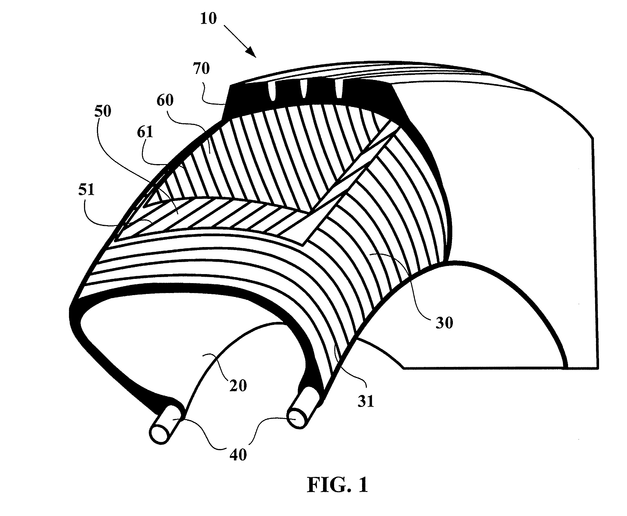
[0033]FIG. 1 schematically represents the structure of a radial pneumatic tire 10 comprising an inner liner 20 made of airtight synthetic rubber, a carcass ply 30 composed of textile cords 31, laid down in straight lines and sandwiched in rubber, bead wires 40 holding the tire 10 onto the rim (not illustrated), a breaker belt made of at least two radially adjacent breaker plies 50 and 60, and a tread 70 laid over the breaker plies 50 and 60 to be in contact with the road. Each of the two breaker plies 50 and 60 of tire 10 is reinforced with steel cords 51 and 61 that are inclined with respect to the equatorial plane of the tire at an appropriate angle (typically around 20°). In this embodiment, the cords 51 of one ply are inclined oppositely to the cords 61 of the other ply.

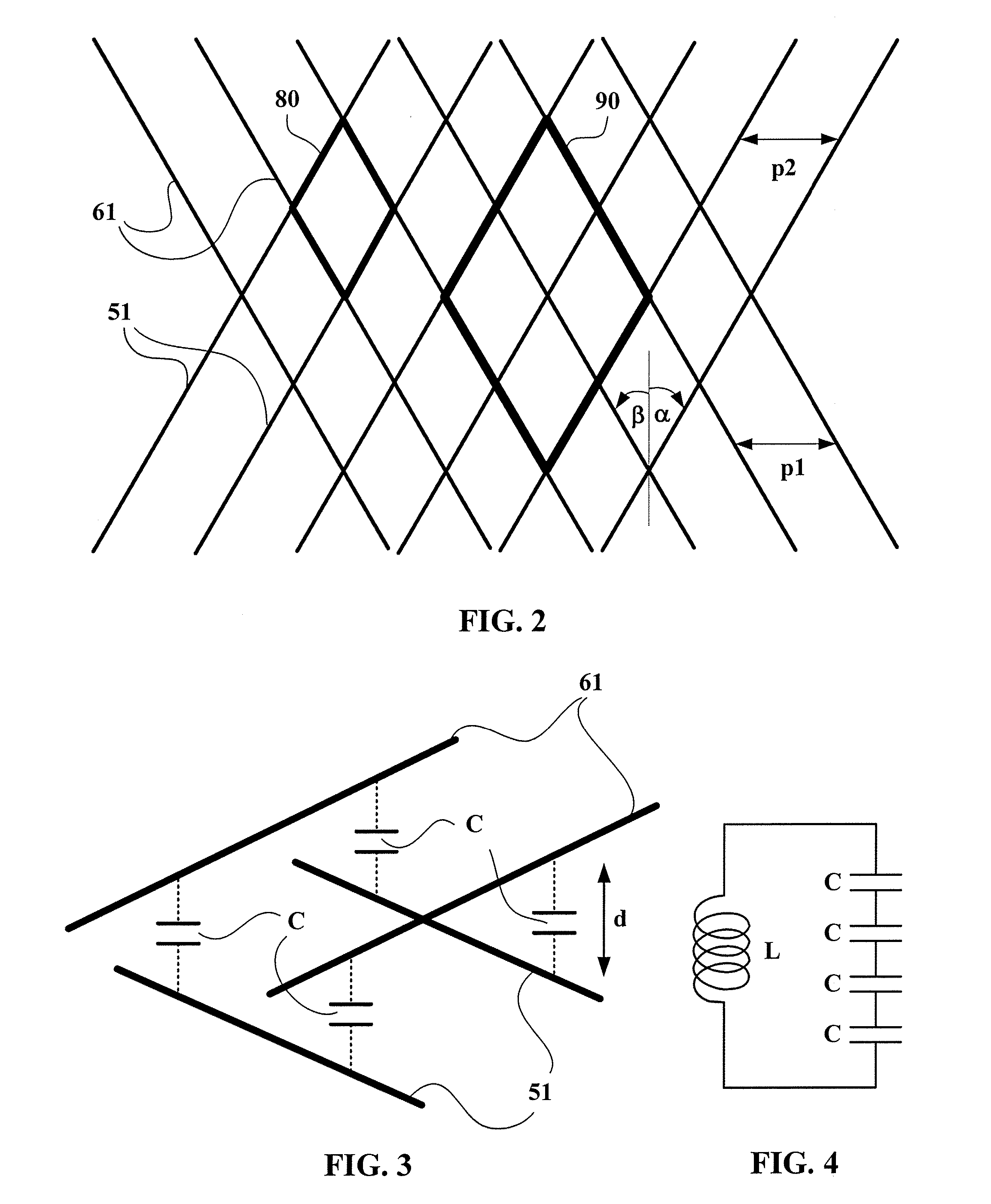
[0034] This particular arrangement of the plies included in the breaker belt explains the strong absorption of electromagnetic radiation in the belt. As schematically represented in FIG. 2, the sets of cords 51 ...


PUM


Abstract

A tire including a tread and a belt having a first and a second ply. The first and second plies are made up of substantially parallel metallic reinforcing cords embedded in a rubber composition that are inclined with respect to the equatorial plane of the tire, and the cords of the first ply are inclined with respect to the cords of the second ply. At least one dipolar electric element connects at least one cord of the first ply to at least one cord of the second ply. The path followed by the dipolar electric element between the cord of the first ply and the cord of the second ply extends into a part of the tread so as to be worn away before or upon reaching a tread wear limit.

Description

CROSS-REFERENCE TO RELATED APPLICATION [0001] This application claims the benefit of U.S. Provisional Application No. 60 / 771,043, filed Feb. 6, 2006, which is incorporated herein by reference in its entirety.BACKGROUND OF THE INVENTION [0002] 1. Field of the Invention [0003] The present invention concerns tire wear control, and in particular, tires that allow automatic detection that a predetermined tire wear threshold has been reached. [0004] 2. Related Art [0005] As used herein, the term “cord” is understood to mean a single thread or wire, metallic or non metallic, or an assembly of several threads or wires. “Ply” refers to a layer of parallel reinforcing cords, metallic or non metallic, woven or unwoven, and embedded in a rubber composition, the thickness of the ply being close to the diameter of an individual cord. “Belt” refers to an assembly of at least two plies that is unanchored to the bead. “Axial” refers to a direction essentially parallel to the rotation axis of a tire....

Claims


Application Information

Patent Timeline
IPC IPC(8): B60C11/24
CPCY10T152/10027B60C11/24
Inventor MYATT, DAVID
Owner MICHELIN & CO CIE GEN DES ESTAB MICHELIN
Learn More