Loop heat pipe

Inactive Publication Date: 2007-08-02
JAFFE
View PDF0 Cites 7 Cited by
  • Summary
  • Abstract
  • Description
  • Claims
  • Application Information

AI Technical Summary

Benefits of technology

[0006] The present invention is to provide a loop heat pipe, which can ease the operation for cleaning, evacuating or exhausting the loop heat pipe before sealing. In addition, the evaporator and the pipe body of the loop heat pipe of the present invention can be connected with fewer steps.

Problems solved by technology

After the pipes and the evaporator form a loop, it is very difficult to clean, evacuate or exhaust the internal part of the pipes.
Therefore, the cleanness and the degree of vacuum of the pipes become uncontrollable, which will affect the performance of heat transfer.
In this manner, the loop.heat pipe will interfere the welding or the adhesion procedure.
However, the detachable torch requires additional steps for detaching and assembling the torch, which will largely slow down the production speed.
However, the melted soldering material can flow into the pipe, which will be absorbed by the capillary structure, thereby clogging the capillary structure.

Method used


Image

  • Loop heat pipe
  • Loop heat pipe
  • Loop heat pipe

Examples


first embodiment

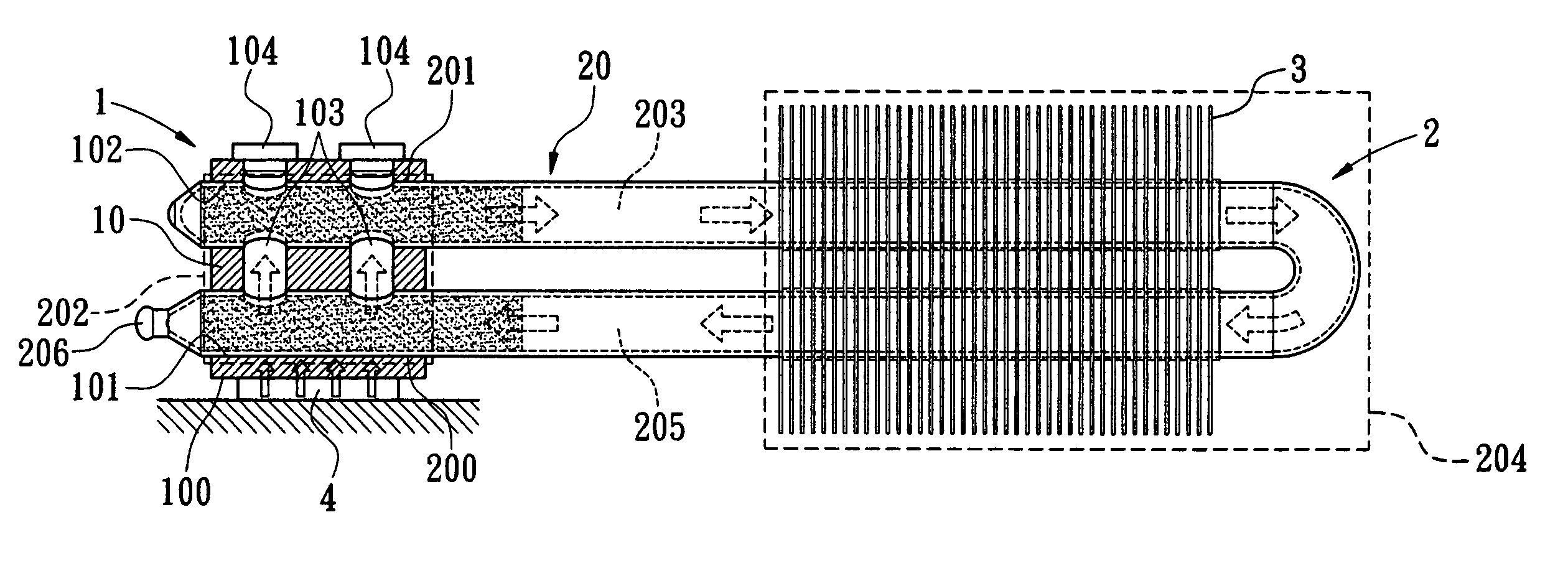
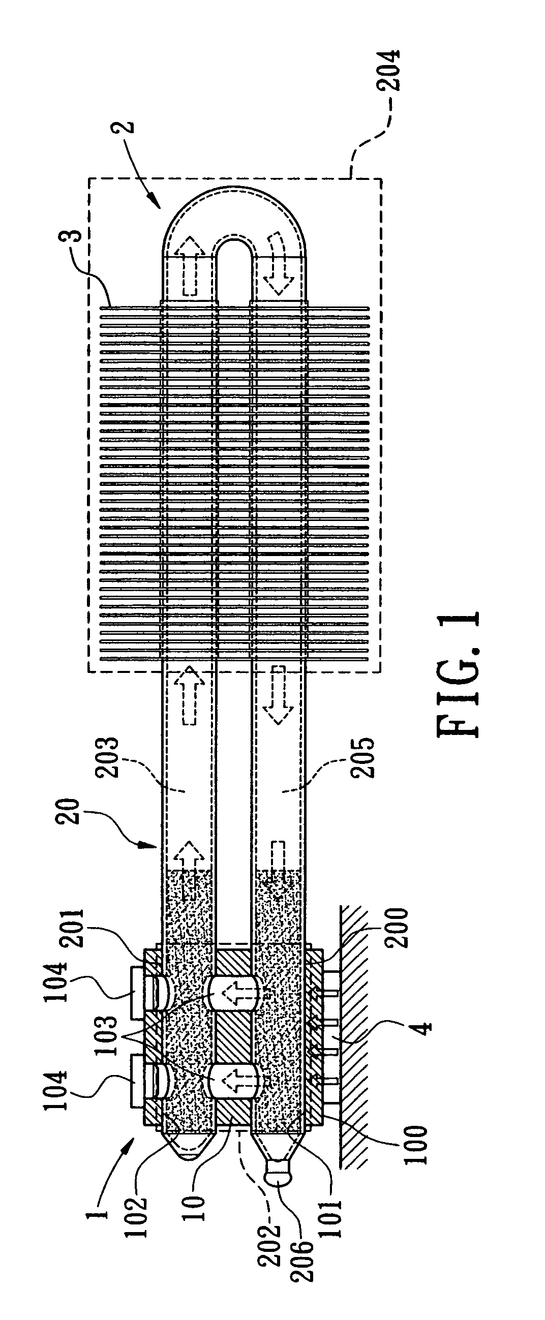
[0014] Referring to FIG. 1, a loop heat pipe in accordance with the present invention is illustrated. As shown, the loop heat pipe includes an evaporator 1 and a sealed pipe 2.

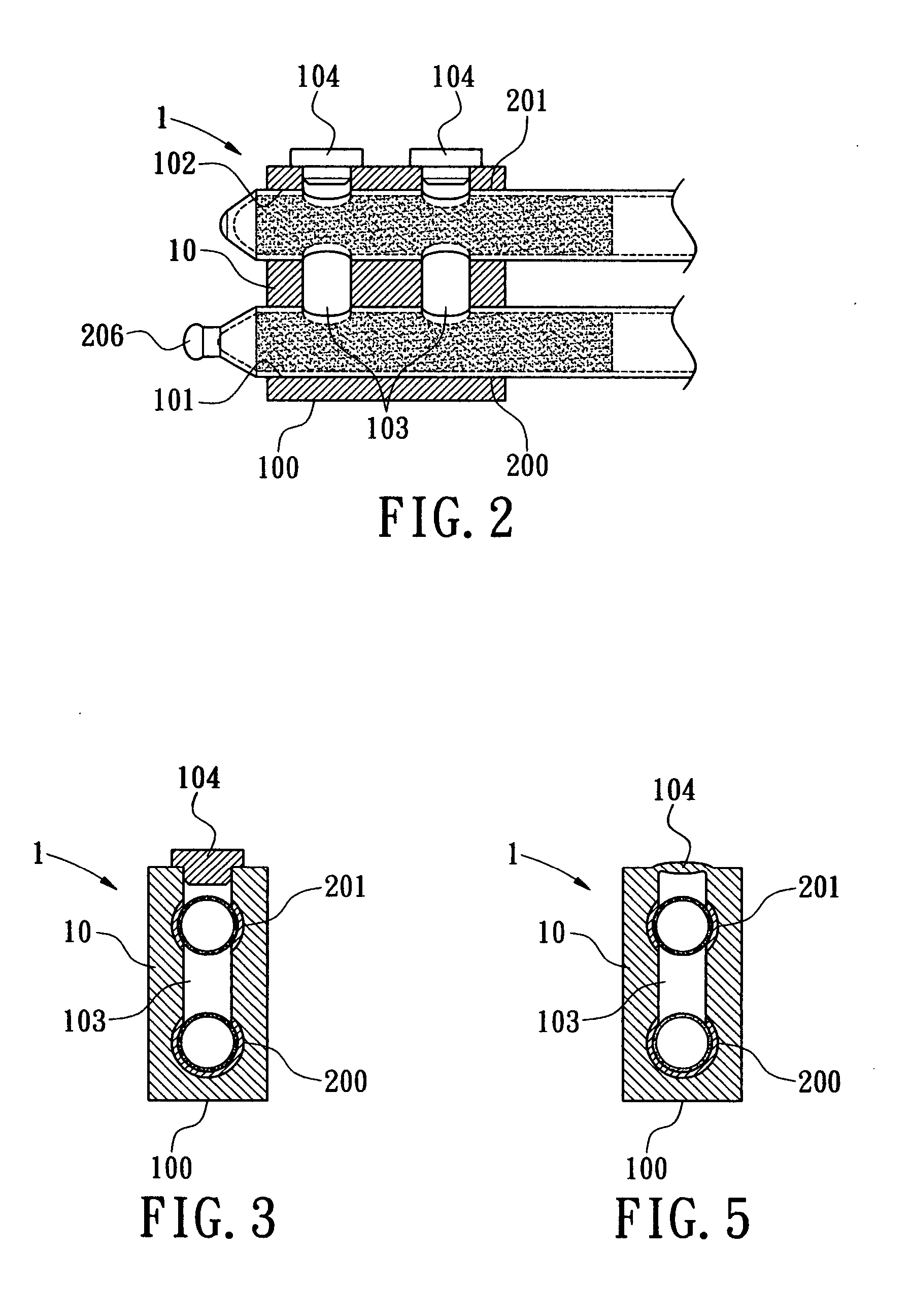
[0015] The evaporator 1 is the portion that the loop heat pipe absorbs heat. The evaporator 1 includes a evaporator body 1 made of a heat conductive material, e.g. aluminum or copper. Therefore, the evaporator body 10 is substantially a heat spreader, which includes a contact surface 100 provided for contacting with a heat source 4. The heat source 4 is a heat generating electronic device. In one embodiment, the heat source 4 refers to the central processing unit. In addition, at least two retaining hole 101, 102 are formed on the evaporator body 10, and at least a channel hole 103 penetrating the retaining holes 101, 102.

[0016] The sealed pipe 2 is a bent pipe body 20. Alternatively, the sealed pipe 2 is composed of two or more pipes 20, 21, 22 (as shown in FIG. 4) sequentially connected to each other. A cap...

second embodiment

[0019] In addition, referring to FIG. 4, a loop heat pipe in accordance with the present invention is illustrated. In this particular embodiment, the sealed pipe 2 includes two or more pipe bodies 20, 21, 22 sequentially connected with each other. Each pipe body, 20, 21, 22 is connected with a connection piece 5. The connection piece 5 provides each pipe body 20, 21, 22 to insert into the two connection holes 50 and to penetrate the two channel holes 51 of the connection hole 50. Meanwhile, a sealed portion 52 is formed outside of the connection piece 5 that penetrates through the channel hole 51. The structure of the sealed portion 52 is similar to that of the evaporator 1. However, the connection piece 5 is not limited to the use of heat conductive materials, because the primary fiction of the connection piece 5 is to communicably connect each pipe body 20, 21, 22.

[0020] In summary, the loop heat pipe of the present invention indeed satisfies the patent ability requirements of the...


PUM


Abstract

A loop heat pipe includes an evaporator and a sealed pipe. The evaporator includes an evaporator body made of a heat conductive material. The evaporator body has at least two retaining holes and at least a channel hole penetrating the retaining holes. In addition, the sealed pipe includes at least two sealed ends. The two sealed ends are securely fastened to the two retaining holes of the evaporator. Meanwhile, at least one of the two retaining holes is a through hole, which penetrates through two sides of the evaporator body, and at least one of the sealed ends protrudes the evaporator via the penetrable retaining hole.

Description

BACKGROUND OF THE INVENTION [0001] The present invention relates generally to a loop heat pipe, and more particularly to the evaporator of the loop heat pipe. [0002] A loop heat pipe is a heat exchange system, wherein both the liquid and gas phase of the working fluid flows along the same direction. The working principle of the loop heat pipe is similar to that of the conventional heat pipe. However, the loop heat pipe does not comprise the drawback that the liquid phase of the working fluid flows along a direction opposite to that of the gas working fluid. Therefore, the performance of the loop heat pipe is much better than that of the conventional heat pipe. [0003] One conventional loop heat pipe is disclosed in Taiwanese Patent Application No. 92130196, entitled “method for manufacturing evaporator of loop heat pipe.” Although the primary subject matter disclosed in this application publication is a method for manufacturing the evaporator of a loop heat pipe, one can easily reali...

Claims


Application Information

Patent Timeline
IPC IPC(8): H05K7/20
CPCH01L23/427F28D15/0266H01L2924/0002H01L2924/00
Inventor LI, JIA-HAO
Owner JAFFE
Why Eureka
Try Eureka