Crane and method of assembling crane

a crane and crane body technology, applied in the direction of cranes, etc., can solve the problems of high cost of parts and manufacturing, high cost of design, manufacturing, and storage of rotating frames, and achieve the effect of low total productivity (assemblability) and high cos

Active Publication Date: 2007-08-02
KOBELCO CONSTR MASCH CO LTD
View PDF15 Cites 25 Cited by
  • Summary
  • Abstract
  • Description
  • Claims
  • Application Information

AI Technical Summary

Benefits of technology

[0028] The present invention provides a crane that can easily solve the above problems, that is to say, a crane including a rotating frame such that total productivity (assemblability) can be improved, the cost can be reduced, and model change can be facilitated.
[0046] Therefore, the sharing of a common rotating frame by a plurality of models can be utilized, and this crane has a great advantage in many aspects such as cost, productivity, inventory control, and model change.

Problems solved by technology

However, the crane and method for assembling the same disclosed in Patent Document 1 have the following problems.
Since it is necessary to use so many types of rotating frames, that is to say, the same number of rotating frames as models, the costs of the design, manufacturing, and storage of the rotating frames 3 are high.
Therefore, the costs of the parts and manufacturing are also high.
Moreover, since it is necessary to use different rotating frames 3, parts, and equipments for different models, total productivity (assemblability) is very low.

Method used


Image

  • Crane and method of assembling crane
  • Crane and method of assembling crane
  • Crane and method of assembling crane

Examples


first embodiment

See FIGS. 1 to 6

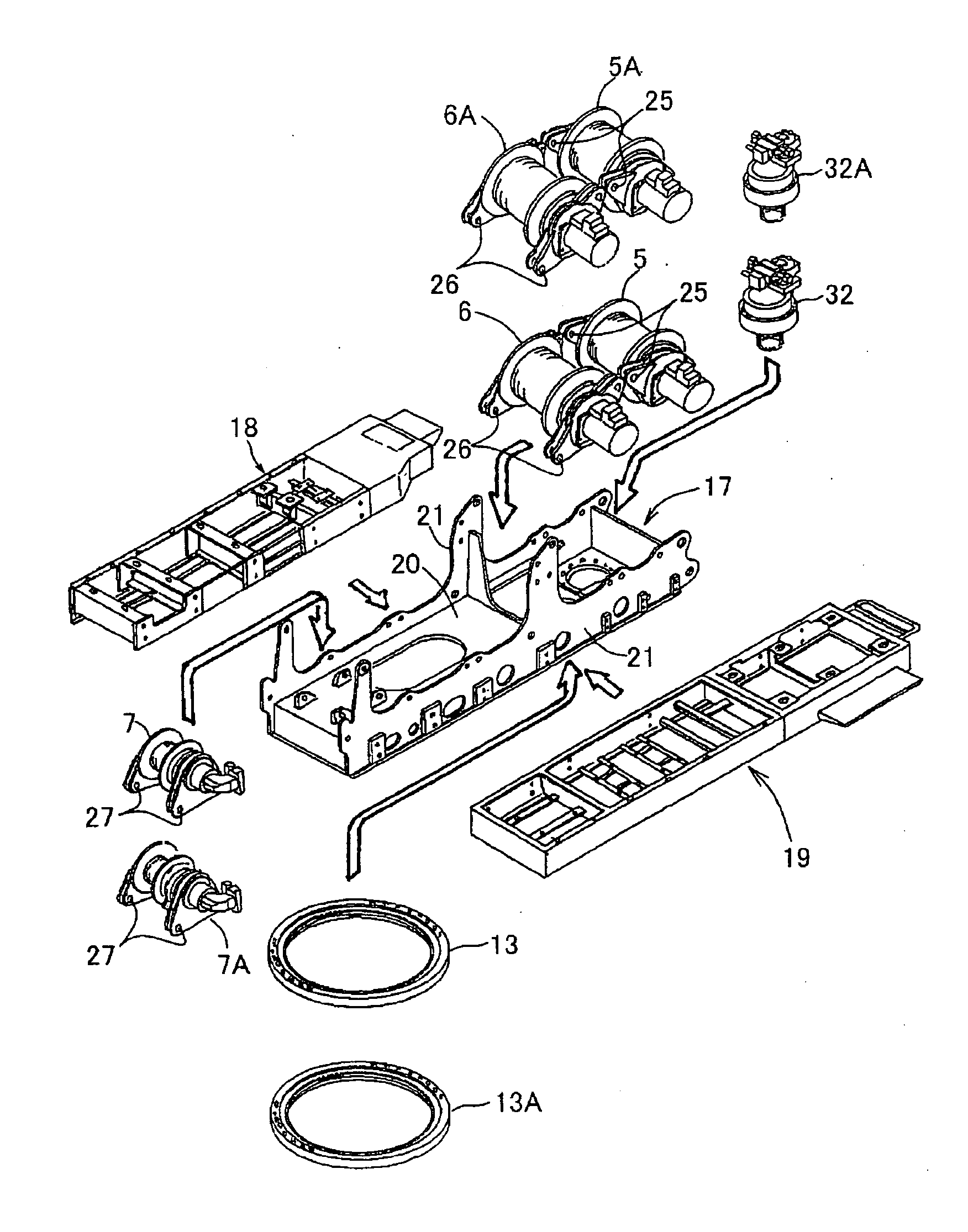
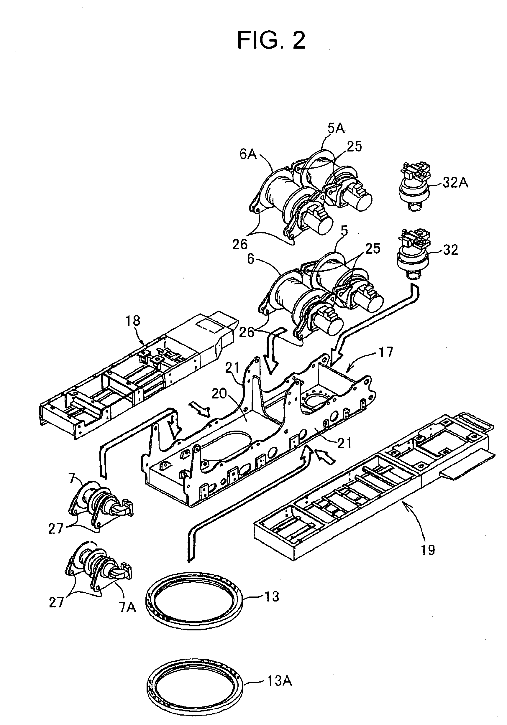
[0069] The upper rotating body of the crane according to this embodiment has a rotating frame 17 shown in FIGS. 1 to 3, which serves as a base. Left and right deck frames 18 and 19 shown in FIGS. 2, 4, and 5 are provided on both the left and right sides of the rotating frame 17.

[0070] Each component will hereinafter be described.

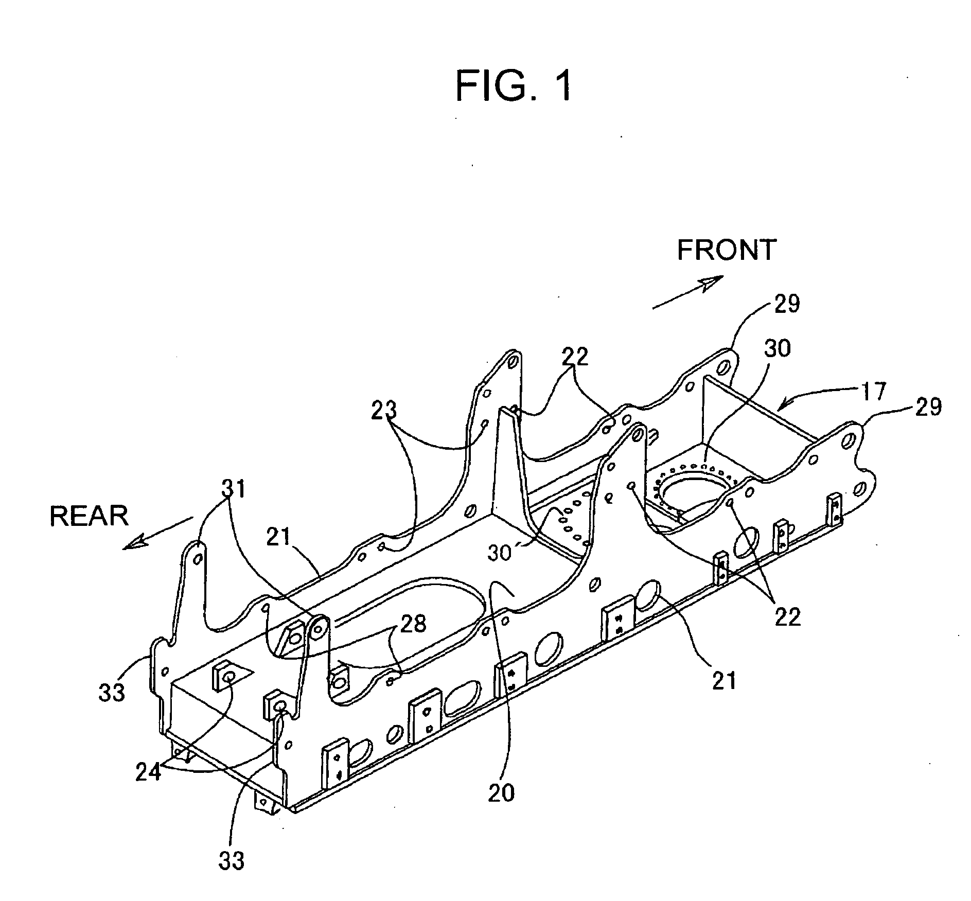
(i) Rotating Frame 17

[0071] As shown in FIG. 1, the rotating frame 17 includes a bottom plate 20 and left and right side plates 21, 21 as main components. The rotating frame 17 has a generally elongated rectangular shape as viewed from above.

[0072] Many crane models having different lifting capacities are divided into a plurality of classes, each class including a plurality of models. In each class, the shape and size of the rotating frame 17 are determined on the basis of the model having the largest lifting capacity.

[0073] More specifically, for example, all models whose lifting capacities range from tens of tonnes to hundreds of tonne...

second embodiment

See FIGS. 7 to 19

[0118] The second embodiment can be carried out in combination with the first embodiment. However, for the sake of convenience, the second embodiment will be described as a separate embodiment. In the second embodiment, the same reference numerals will be used to designate the same components as those in the first embodiment, so that the description will be omitted.

[0119] In the second embodiment, as in the first embodiment, models in the same class share a common rotating frame 17. The mast apparatus 8 and the gantry apparatus 9 serving as boom raising and lowering apparatuses are mounted on the rotating frame 17 with common mounting portions. With respect to the winches 5 to 7 and 12, a plurality of types of winches having different sizes are mounted on the rotating frame 17 with a common mounting portion.

[0120] The upper rotating body shown in FIG. 7 uses a mast apparatus 8 as a boom raising and lowering apparatus, and has three winches: a main winch 5, a subwi...


PUM


Abstract

[PROBLEMS] To provide a rotating frame of an upper rotating body such that total productivity can be improved, the cost can be reduced, and model change can be facilitated. [MEANS FOR SOLVING PROBLEMS] Many models having different lifting capacities are divided into a plurality of classes each including a plurality of models. A rotating frame 17 is determined on the basis of the model having the largest lifting capacity in each class. An upper rotating body is constructed using the rotating frame 17 as the base. In addition, each of winches 5 to 7 is mounted on the rotating frame by using a mounting structure standardized in the same class. On the other hand, left and right deck frames 18 and 19 are divided into sections on which different pieces of equipment are mounted, and the sections are separately attached to the rotating frame 17.

Description

TECHNICAL FIELD [0001] The present invention relates to a mobile crane such as a crawler crane or a wheel crane and a method for assembling the same. BACKGROUND ART [0002] A crawler crane will be described as an example. [0003] As shown in FIG. 20, a crawler crane includes a crawler-type lower traveling body 1 and an upper rotating body 2 mounted thereon rotatably around a vertical axis. [0004] The upper rotating body 2 includes a rotating frame 3 shown in FIG. 21, which serves as a base. Deck frames (not shown) are attached to both the left and right sides of the rotating frame 3. A boom 4 that can be raised and lowered, three winches (a main winch 5, a subwinch 6, and a boom raising and lowering winch 7), a boom raising and lowering apparatus that raises and lowers the boom 4, and other various necessary pieces of equipment are mounted on the rotating frame 3 and the deck frames. [0005] Many crane models having different lifting capacities are manufactured according to country-spe...

Claims


Application Information

Patent Timeline
Patent Type & Authority Applications(United States)
IPC IPC(8): B66C23/44B66C23/36B66C23/62B66C23/82
CPCB66C23/82B66C23/62
Inventor YOKOYAMA, SHOZOMURATA, TOMOHIKOONUKI, KENJISATO, HIROHITOWAKAMATSU, KUNIOGOTO, SHINJIKOBAYASHI, YUTAKAMIYA, EIJI
Owner KOBELCO CONSTR MASCH CO LTD
Why Eureka
Try Eureka