Positioning system, positioning method, and program thereof

a positioning system and positioning method technology, applied in the field of positioning technique for identifying the position of indoor wireless terminals, can solve the problems of high installation cost of infrastructure using bluetooth or rfid systems, low service coverage where wireless lans are used to achieve highly accurate positioning, etc., and achieve low cost and facilitate attachment to ceilings

Inactive Publication Date: 2007-08-02
NEC CORP
View PDF40 Cites 63 Cited by
  • Summary
  • Abstract
  • Description
  • Claims
  • Application Information

AI Technical Summary

Benefits of technology

[0009] An object of the present invention is therefore to provide a technique to realize a positioning system for identifying the position of an indoor-use terminal at low cost.
[0012] Preferably, in the positioning system according to the present invention, the position estimation means estimates the position of the terminal based on one or more unique information that the terminal has received within a past predetermined time period. Preferably the position estimation means estimates the position of the terminal based on the unique information that the terminal has received most recently. Preferably the position estimation means estimates the position of the terminal based on most frequently received unique information among one or more unique information that the terminal has received within a past predetermined time period. Preferably the position estimation means adds a weighting value to one or more unique information that the terminal has received within a past predetermined time based on the reception time of the respective unique information and estimates the position of the terminal based on unique information selected based on a result of the addition. Preferably the position estimation means increases the weighting value as the reception time becomes newer, selects unique information having the largest value resulting from the addition, and estimates the position of the terminal based on the selected unique information.
[0051] According to the present invention, a system uses an illumination device to transmit unique information, uses a terminal to receive the unique information, and estimates the position of the terminal based on the unique information transmitted from the terminal. This configuration eliminates the need to provide a power source for a positioning infrastructure, facilitates attachment to a ceiling, thereby realizing the positioning infrastructure at a low cost.

Problems solved by technology

A first problem is that service coverage where a wireless LAN is used to achieve highly accurate positioning is low.
A second problem is that installation cost of an infrastructure using a Bluetooth or RFID system is high.

Method used


Image

  • Positioning system, positioning method, and program thereof
  • Positioning system, positioning method, and program thereof
  • Positioning system, positioning method, and program thereof

Examples


first embodiment

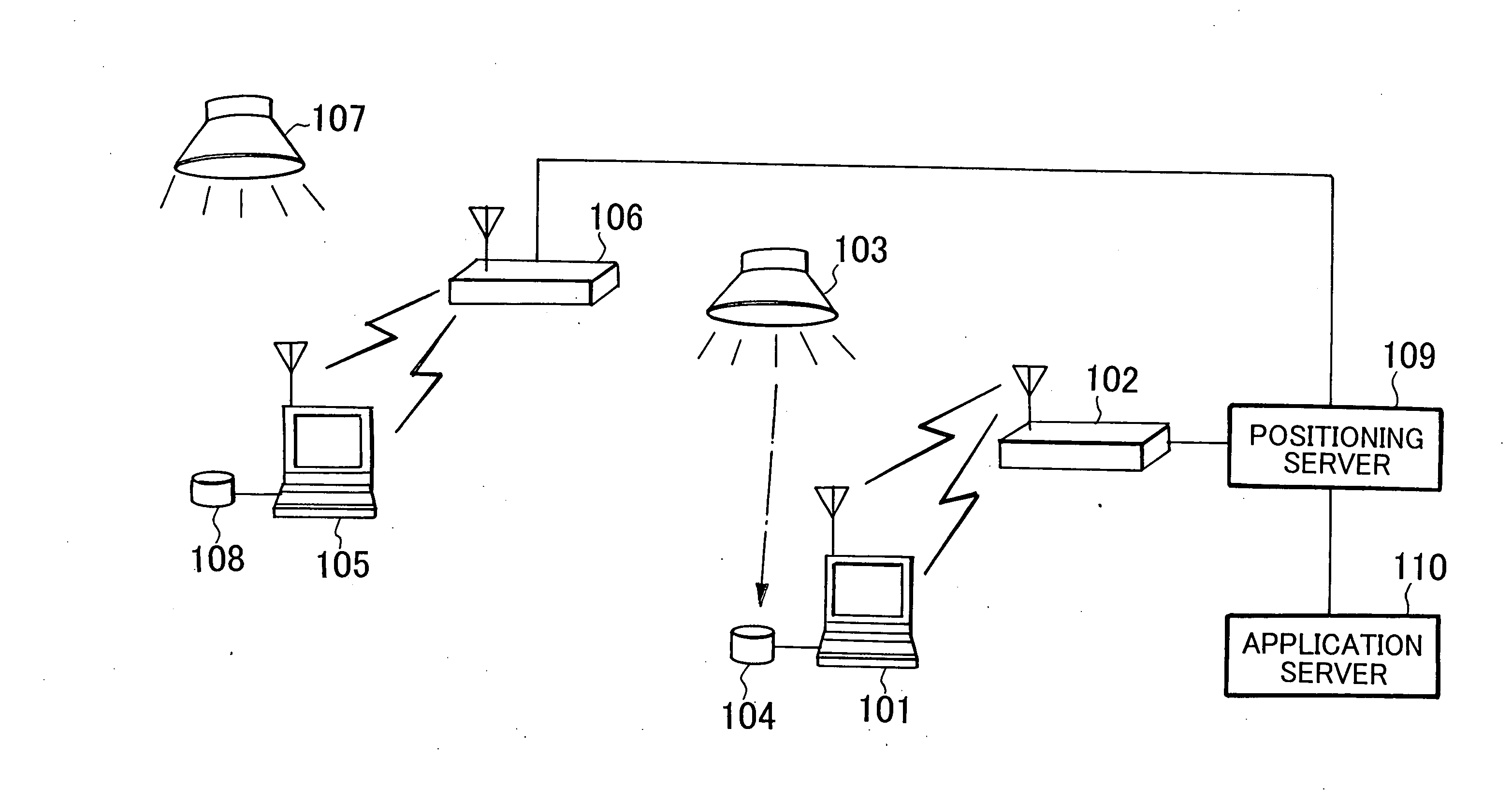
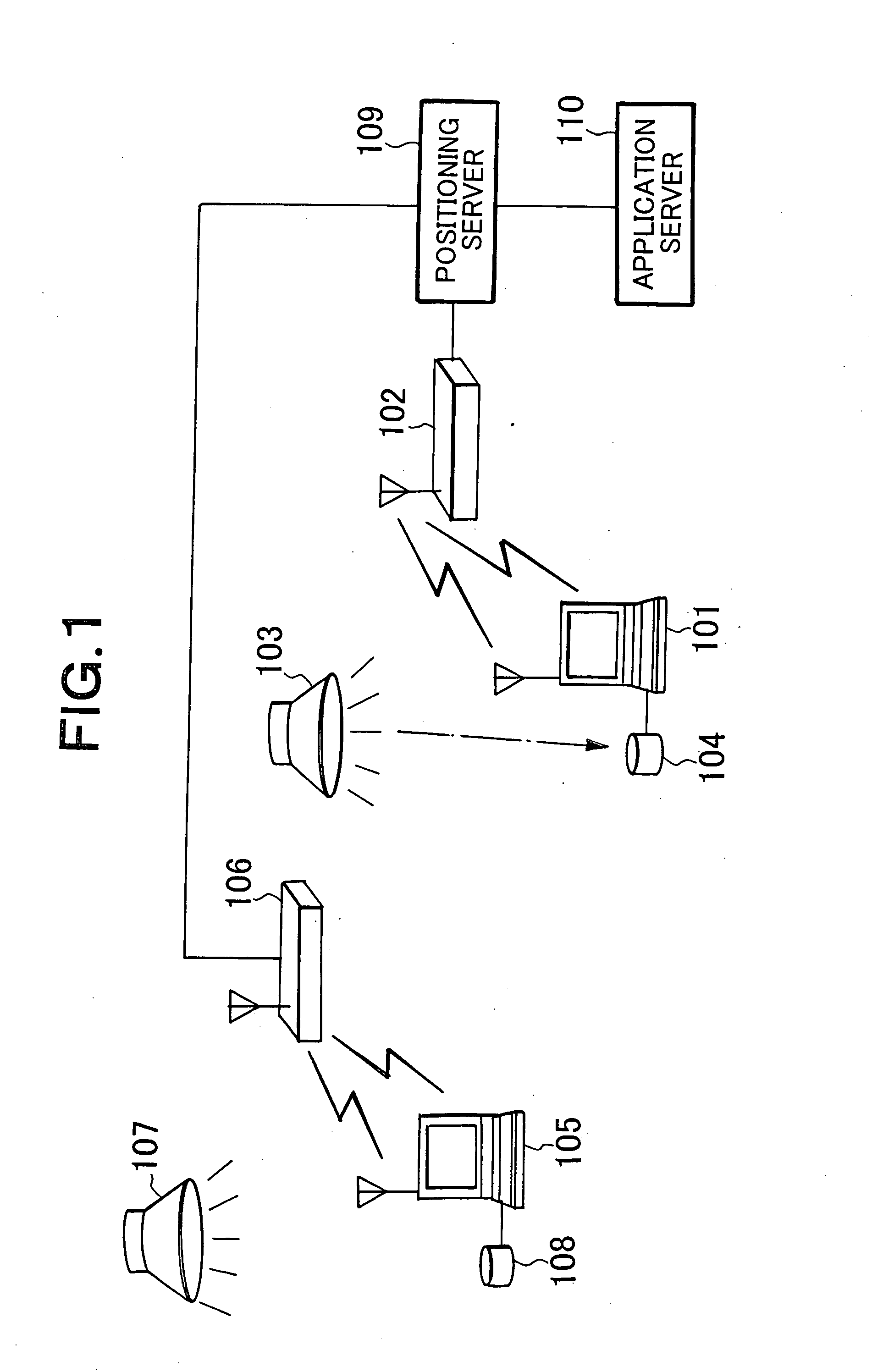
[0132]FIG. 1 is a view showing the entire configuration of a positioning system according to a first embodiment. The positioning system of the first embodiment shown in FIG. 1 includes: a plurality of terminals 101 and 105 connected to light signal detection units 104 and 108; a plurality of base stations 102 and 106 which perform wireless communication between themselves and terminals 101 and 105; a plurality of illumination devices 103 and 107 which transmit unique information as a light signal capable of being detected by the light signal detection units 104 and 108; one or more positioning servers 109 (In FIG. 1, one positioning server 109 is provided) connected to the base stations 102 and 106 in a communicable manner; and one or more application servers 110 (In FIG. 1, one application server 110 is provided) connected to the positioning server 109 in a communicable manner. The positioning server 109 and application server 110 may be integrated as a single unit. Although not sh...

second embodiment

[0241] As an embodiment different from the above first embodiment, a configuration that allows a positioning system using a wireless LAN and positioning system using an illumination device to work together in a switchable manner will be described as a second embodiment. In this embodiment, the same reference numerals as the first embodiment are given to the components which are common to the first embodiment, and the overlapped description is omitted. Since the second embodiment is basically the same as the first embodiment, the description will be given focusing on the differences from the first embodiment. The second embodiment differs from the first embodiment in the internal configuration of the positioning server 109 shown in FIG. 1.

[0242]FIG. 15 shows a configuration example of the positioning server 109 used in the case where a positioning system using a wireless LAN and positioning system using an illumination device are allowed to work together.

[0243] The positioning serv...

third embodiment

[0310] As is clear from the above description, the positioning server according to the present invention can be realized not only by hardware, but also by a computer program.

[0311]FIG. 21 is a block diagram showing a configuration example of an information processing system that implements the positioning server according to the present invention.

[0312] The information processing apparatus shown in FIG. 21 includes a processor 2101, a program memory 2102, and a recording medium 2103. As the recording medium, a magnetic recording medium such as a hard disk can be employed.


PUM


Abstract

A positioning system includes an illumination device, a terminal, and a positioning server. The illumination device transmits identification information. The terminal transmits the identification information received from the illumination device, to the positioning server. The positioning server uses the identification information received from the terminal, thereby searching an illumination installation position database registered in advance so as to identify the terminal position. This eliminates power supply for positioning infrastructure and facilitates attachment to a ceiling, thereby realizing the positioning infrastructure at a low cost.

Description

TECHNICAL FIELD [0001] The present invention relates to a positioning technique for identifying the position of a wireless terminal and, more particularly, to a positioning technique for identifying the position of an indoor wireless terminal. Background Art [0002] In a cellular system, a positioning technique for identifying the position of a terminal using a signal from a plurality of GPS (Global Positioning System) satellites or a plurality of base stations has been used. This technique can identify the position of a terminal with an accuracy of about 10 to 100 m. [0003] However, in an indoor environment, it is difficult to receive a signal from GPS satellites or base stations needed for position identification, preventing highly accurate identification of the terminal position. [0004] As a technique for identifying the position of a terminal used in an indoor environment, there are known positioning techniques such as one using a signal of a wireless LAN (Local Area Network) ins...

Claims


Application Information

Patent Timeline
Patent Type & Authority Applications(United States)
IPC IPC(8): G01B11/14G01S1/70G01S5/00G01S5/16H04B7/26H04B10/11H04B10/116H04B10/118H04W52/00H04W64/00
CPCG01S1/70H05B37/029G01S5/16G01S5/0009H05B47/155G01S2201/01G01S1/7034G01S2201/02
Inventor ISHII, KENICHIMATSUDA, JUNICHI
Owner NEC CORP
Why Eureka
Try Eureka