
Scanning illumination system and method

a scanning illumination and illumination system technology, applied in the field of scanning illumination systems, can solve the problems of unacceptably high manufacturing cost, unsatisfactory reliability associated with operation, and non-ideal illumination pattern of objects, and achieve the effect of greatly increasing the comparative area-coverag

Active Publication Date: 2007-08-02
DUNCAN WAYNE O
View PDF11 Cites 37 Cited by
  • Summary
  • Abstract
  • Description
  • Claims
  • Application Information

AI Technical Summary

Benefits of technology

[0016]One advantage of the present system is the projection of an illumination pattern that appears to have the intensity of a spot beam shown over a broad area. Another advantage of the present invention is apparent when comparing the area that is illuminated by a circle of light, such as displayed by existing illumination systems such as but not limited to a flashlight, compared with the polygonal illumination pattern of the current invention. When comparing a circular light pattern having a diameter of eight (8) inches and a subsequent area of 50.24 square inches, using the formula pi (3.14) times the radius squared, to a simple polygon, the square, having a width of eight (8) inches and a subsequent area of 64 square inches, the square-shaped illuminated area covers an additional 13.76 square inches, or 27% more area-coverage. It is easily understood that if a rectangular-shaped illumination pattern with the narrow rectangular dimension of 8 inches were being illustrated, the comparative area-coverage would be greatly increased.

Problems solved by technology

This resultant broad beam creates a non-ideal illumination pattern on objects that are to be illuminated.
The undue complexity of these designs leads to unacceptably high manufacturing costs and to issues of reliability associated with their operation.
The physical wear on the components, motors, and gears, and the power supply necessary to power the motors and galvanometers, render such designs unpractical for most extended-use purposes.
This one-dimensional spinning scanner can only minimize the typically non-illuminated area, while still only generating a weaker broad beam, and produces the standard problems with physically whirling, motorized mechanisms.
This design is not intended for portable use, is encumbered by the usual downfalls of spinning and mechanical motors, and requires a non-economical and impractical power supply.
These devices are usually very expensive, rarely portable, and are designed to reflect a large spot-beam of light back onto a screen, blocking or partially blocking chosen pixel-size elements to project black and gray-scale spots in those chosen pixel areas.
In either case, the intensity of the light would not be suitable for an illumination device and the cost of the accompanying electronics would be prohibitive for most illumination applications.
Some systems exist that use a two-dimensional micro-mirror device to eliminate the use of the galvanometer motors, but these systems are generally considered fixed systems designed to project line drawings, and are not usable for general illumination applications.

Method used


Image

  • Scanning illumination system and method
  • Scanning illumination system and method
  • Scanning illumination system and method

Examples


Embodiment Construction

)

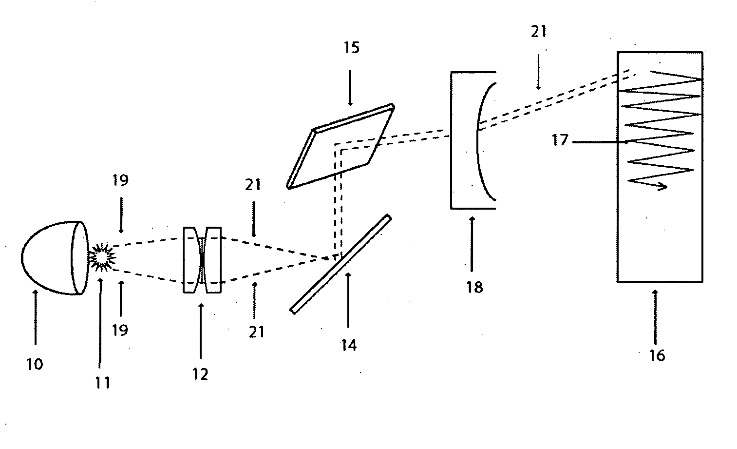
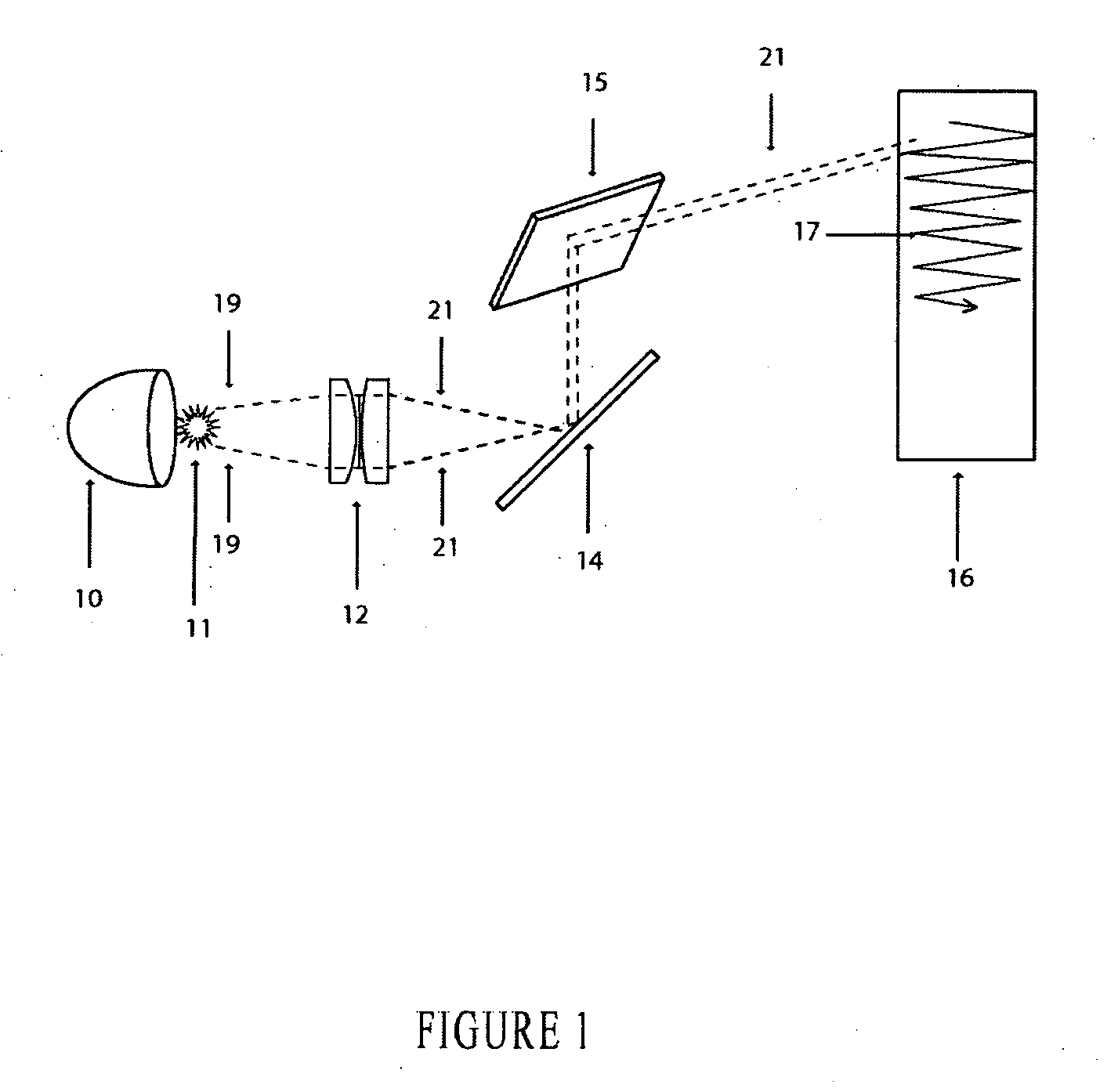
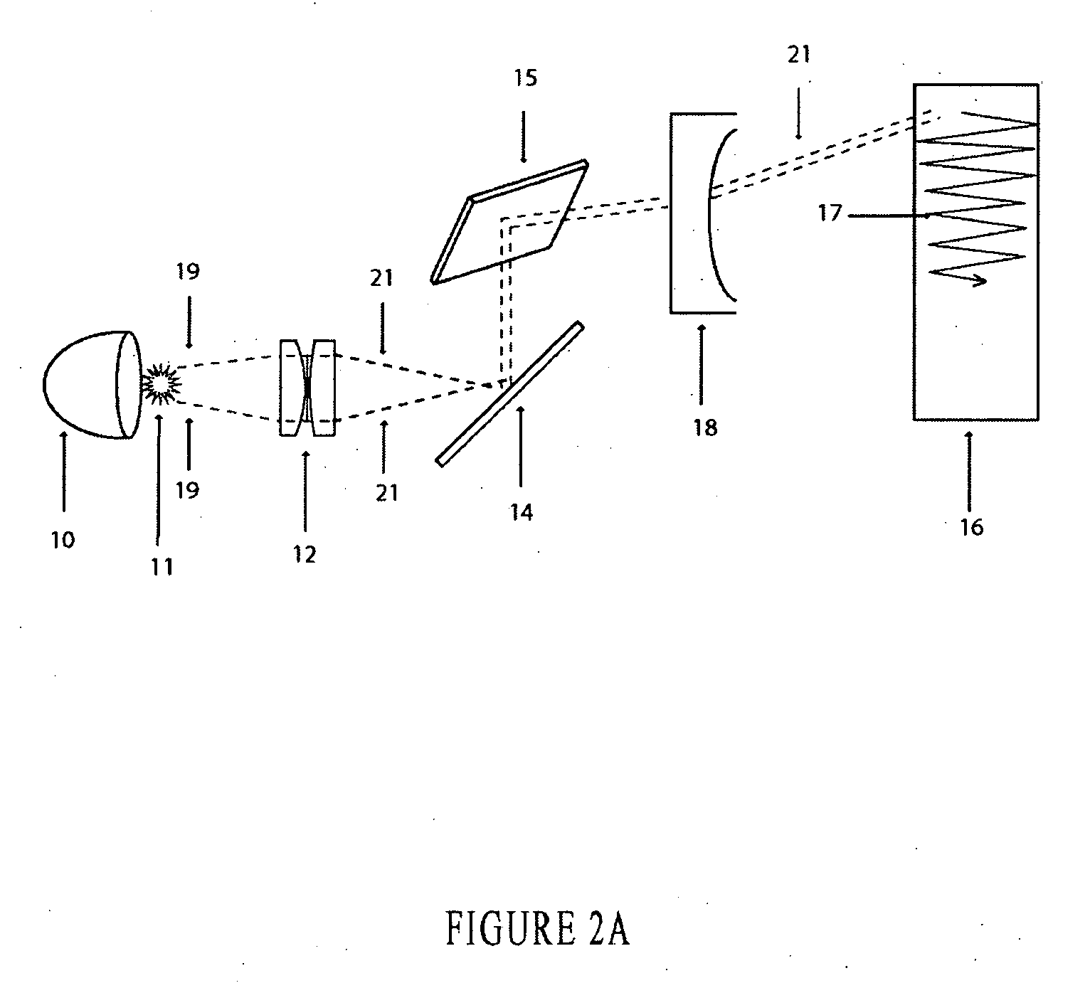
[0034]A preferred embodiment of the current invention, depicted in FIG. 1, utilizes one element of beam-shaping optics 10 as it collects and reflects the light from light source 11 through beams 19 into another stage of the beam shaping optics, plano-convex lenses 12. The resulting beams 21 leave the beam-shaping optics and arrive at fold back mirror 14. The light is thereby directed by fold back mirror 14 onto beam-steering device 15, a two-dimensional micro-mirror in the preferred embodiment. Beam-steering device 15 scans light beam 21 in a horizontal and vertical pattern toward targeted area 16, resulting in an apparent solid illumination pattern 17 of a polygonal shape.

[0035]A related alternative embodiment of the current invention, not shown, includes a collimating lens, as known in the art, between plano-convex lenses 12 and fold back mirror 14 for further beam shaping. In another alternative embodiment of the current invention, fold back mirror 14, added to conserve space in...


PUM


Abstract

A method and apparatus for the multi-dimensional control of a light source's brightest point over a targeted area is disclosed. Control and drive electronics are presented to the beam-steering device causing the beam-steering component to steer the spot of light toward a targeted area in at least a two-dimensional scanning pattern about a vertical and horizontal axis. The result is an illuminated pattern displayed on a targeted area that appears to be a solid, uniformly illuminated light pattern, having the intensity of a spot beam and the area of a broad beam.

Description

CROSS-REFERENCE TO RELATED APPLICATIONS[0001]This application claims priority from U.S. Provisional Patent App. No. 60 / 763,245, entitled “Square Beam Light Delivery System” and filed on Jan. 30, 2006, the entire disclosure of which is incorporated herein by reference.STATEMENT REGARDING FEDERALLY SPONSORED RESEARCH OR DEVELOPMENT[0002]Not applicable.BACKGROUND OF THE INVENTION[0003]1. Field of the Invention[0004]The present invention relates to illumination systems, and in particular to illumination systems wherein a light source is scanned across a targeted area at a rapid speed such that the entire illuminated pattern appears to be simultaneously illuminated by the light source.[0005]2. Brief Description of the Related Art[0006]Using conventional portable and fixed illumination devices, such as a flashlight or an automobile headlamp, respectively, the light that is cast onto a target is brightest in the center, and loses intensity as it reaches the outside of the light pattern gen...

Claims


Application Information

Patent Timeline
IPC IPC(8): G02B26/08
CPCG02B26/101
Inventor DUNCAN, WAYNE O.
Owner DUNCAN WAYNE O
Learn More