
Apparatus and method for transmitting a signal in a communication system

a communication system and apparatus technology, applied in the direction of electrical apparatus, antennas, electrical long antennas, etc., can solve the problems of system power consumption, low efficiency of transmission paths, and low efficiency of channel combiners used at outputs of scpas, so as to improve cost competitiveness, reduce complexity of wireless communication systems, and increase the efficiency of transmission paths

Inactive Publication Date: 2007-08-02
SAMSUNG ELECTRONICS CO LTD
View PDF11 Cites 4 Cited by
  • Summary
  • Abstract
  • Description
  • Claims
  • Application Information

AI Technical Summary

Benefits of technology

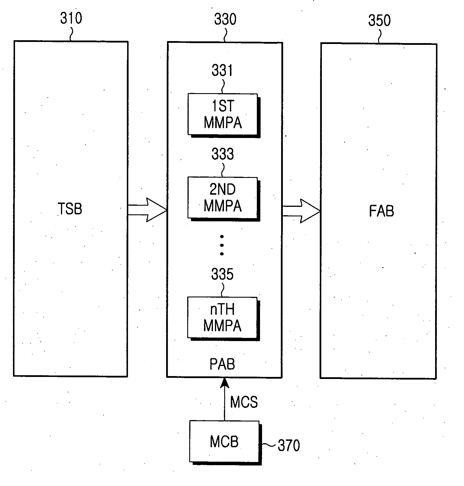
[0025] Another object of the present invention is to provide a configuration of a wireless communication base station system using a multi-path / multi-mode power amplifier capable of decreasing complexity of a wireless communication system.
[0026] Further another object of the present invention is to provide a structure of a power amplifier supporting multiple paths and multiple modes capable of increasing efficiency of transmission paths and cost competitiveness according to an environment of a wireless communication system, and a signal transmission method using the same.

Problems solved by technology

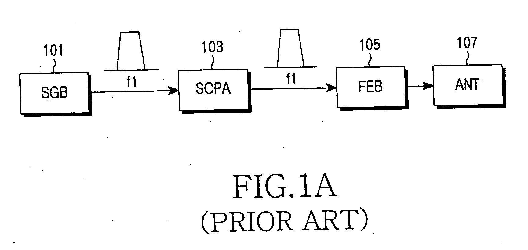
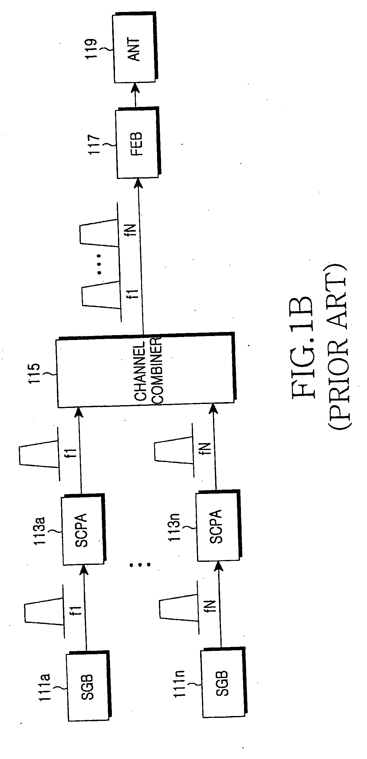
However, the channel combiner used at outputs of the SCPAs has a very high insertion loss, and can hardly combine adjacent FAs.
In terms of the same antenna output, the SCPAs, compared with the MCPA, increase in system power consumption due to the insertion loss of the channel combiner, requiring a higher system cooling capability and thus increasing the system operating cost.
In the communication system with limited number of antennas, as the MCPA does not use a channel combiner even though the number of FAs in operation increases, the MCPA, compared with the SCPAs, decreases in power consumption in terms of the same antenna output.
Therefore, the MCPA requires a lower cooling capacity, thereby increasing competitiveness in the system implementation cost and the system operating cost.
Generally, however, the MCPA is higher than the SCPA in price per unit, and in a system with less number of FAs in operation, the MCPA uses only its partial capacity inefficiently, thereby increasing the initial system installation cost.
In addition, when the system operates with less number of FAs so that it can use the SCPAs without channel combiner, the use of the MCPA is disadvantageous over the use of the SCPAs in terms of the efficiency.
Therefore, competitiveness of the system considerably decreases in terms of cost, structure and size.
In addition, even when the signal transmission apparatus with Smart Antenna or MIMO scheme is implemented with MCPA, the signal transmission apparatus should use a plurality of transmission antennas, so it needs as many MCPAs as the number of antennas, decreasing competitiveness of the system in terms of the cost, structure and size.

Method used


Image

  • Apparatus and method for transmitting a signal in a communication system
  • Apparatus and method for transmitting a signal in a communication system
  • Apparatus and method for transmitting a signal in a communication system

Examples


Embodiment Construction

[0040] A preferred embodiment of the present invention will now be described in detail with reference to the annexed drawings. In the drawings, the same or similar elements, features and structures are denoted by the same reference numerals even though they are depicted in different drawings. In the following description, a detailed description of known functions and configurations incorporated herein has been omitted for clarity and conciseness.

[0041] The present invention provides a Radio Frequency (RF) power amplifier applied to a Base Station (BS) of a communication system, and a signal transmission apparatus using the same.

[0042] Specifically, the present invention provides to a Multi-path / Multi-mode RF Power Amplifier (MMPA) that has several RF amplification paths for one RF power amplifier and operates in two modes of a Single-Carrier Power Amplifier (SCPA) mode and a Multi-Carrier Power Amplifier (MCPA) mode, and provides a signal transmission apparatus and method for tran...


PUM


Abstract

A method is provided for transmitting a signal in a signal transmission apparatus of a communication system. Upon receiving a signal, the signal transmission apparatus determines a mode of the received signal, in which a power amplifier should amplify the signal; generates a mode control signal corresponding to a single mode, if the mode of the received signal is determined as the single mode; amplifies and transmits the received signal in the single mode according to the mode control signal; generates a mode control signal corresponding to a multi-mode, if the mode of the received signal is the multi-mode; and amplifies and transmits the received signal in the multi-mode according to the mode control signal.

Description

PRIORITY [0001] This application claims priority under 35 U.S.C. § 119(a) to an application filed in the Korean Intellectual Property Office on Dec. 29, 2005 and assigned Serial No. 2005-133780, the contents of which are incorporated herein by reference. BACKGROUND OF THE INVENTION [0002] 1. Field of the Invention [0003] The present invention relates generally to an apparatus and method for transmitting signals in a communication system, and in particular, to an apparatus and method for transmitting signals using a power amplifier in a communication system. [0004] 2. Description of the Related Art [0005] Generally, a Radio Frequency (RF) power amplifier used in the current communication system is classified into a Single-Carrier Power Amplifier (SCPA) and a Multi-Carrier Power Amplifier (MCPA). [0006] Referring to FIGS. 1A and 1B, a configuration of a general communication system using an SCPA will be described herein. [0007]FIGS. 1A and 1B are diagrams schematically illustrating a ...

Claims


Application Information

Patent Timeline
Patent Type & Authority Applications(United States)
IPC IPC(8): H04B1/04H01Q11/12
CPCH04B1/406H04B1/0483H04B7/155
Inventor YOON, HYUN-SUCHO, SEI-JEI
Owner SAMSUNG ELECTRONICS CO LTD
Learn More