Technique for distinguishing between link and node failure using bidirectional forwarding detection (BFD)

a technology of bidirectional forwarding and node failure, applied in the field of computer networks, can solve the problems of devices breaking, destroying or closing the bgp session, and node becoming unable to communicate with one of its neighboring nodes, so as to minimize the performance of unnecessary node protection techniques and minimize false detection of failed nodes.

Active Publication Date: 2007-08-02
CISCO TECH INC
View PDF17 Cites 64 Cited by
  • Summary
  • Abstract
  • Description
  • Claims
  • Application Information

AI Technical Summary

Benefits of technology

[0021] Advantageously, the novel technique distinguishes between link and node failure using BFD in a computer network. By establishing BFD and additional uBFD sessions from the monitored node along paths diverse from the first link, the novel technique provides the ability to determine whether a link (e.g., or line card) or node has failed depending upon which of the BFD and uBFD sessions remain operational. Accordingly, the present invention minimizes false detection of failed nodes, and thus minimizes performance of unnecessary node protection techniques.

Problems solved by technology

For example, the node may become unable to communicate with one of its neighboring nodes, e.g., due to a link failure between the nodes or the neighboring node failing, such as going “off line,” etc.
Notably, in the event the Hold Time has expired, the devices may “break” (i.e., tear down or close) the BGP session.
One problem with using BFD is that it is difficult to determine whether a monitored node has failed, or if simply the link over which the BFD messages traverse has failed.
Declaring a node down when it is not produces undesirable results in the network, such as improper traffic forwarding, etc., as will be understood by those skilled in the art.
A problem with both proposed solutions above is that, while providing better determination of link versus node failure, they may both lead to false indications when only a portion of a node fails.
For this reason, if the shared resource fails at the node, the above solutions may produce a false indication of node failure.

Method used


Image

  • Technique for distinguishing between link and node failure using bidirectional forwarding detection (BFD)
  • Technique for distinguishing between link and node failure using bidirectional forwarding detection (BFD)
  • Technique for distinguishing between link and node failure using bidirectional forwarding detection (BFD)

Examples


Embodiment Construction

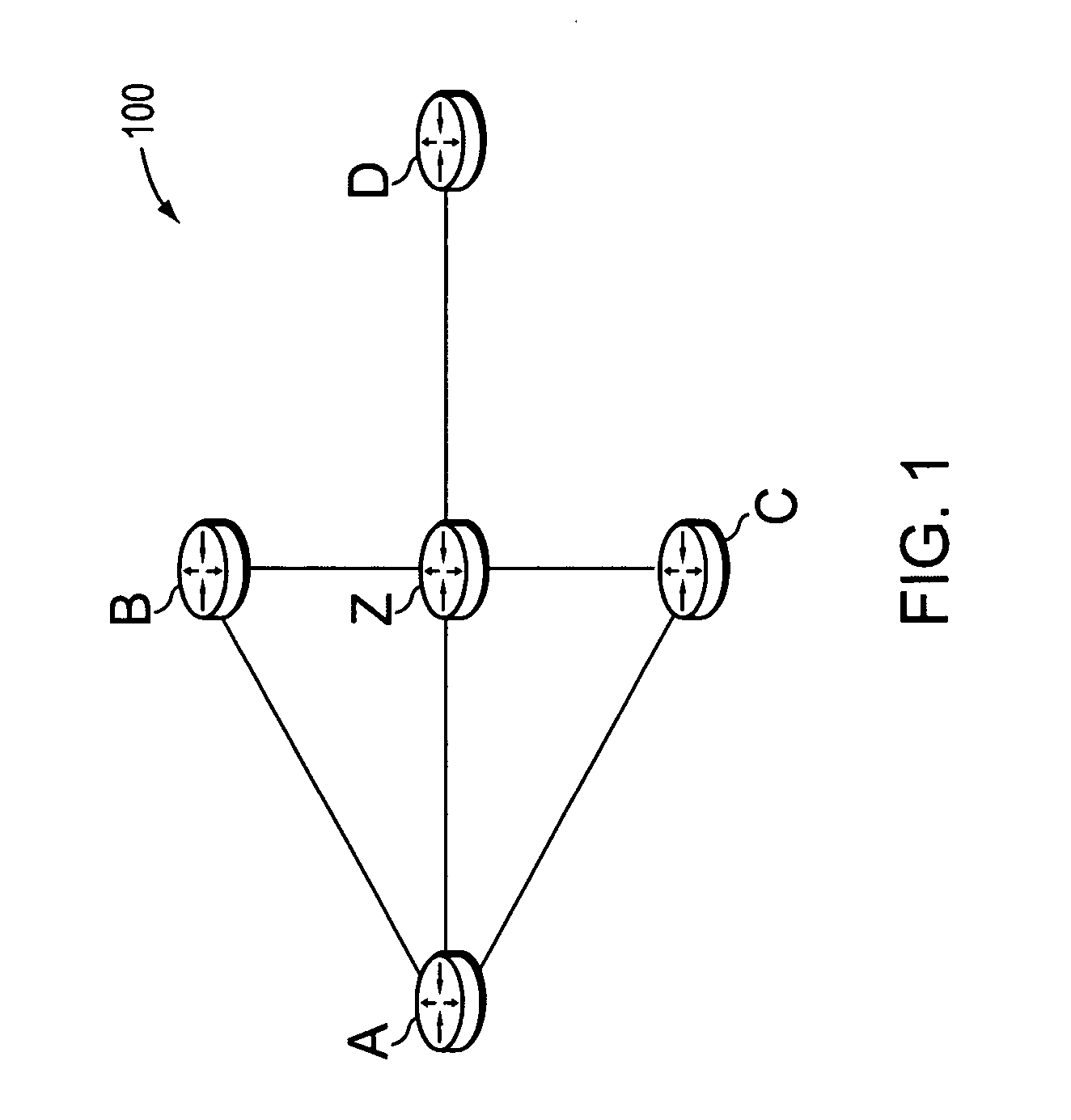
[0028]FIG. 1 is a schematic block diagram of an exemplary computer network 100 comprising a plurality of nodes A-D and Z, such as routers or other network devices, interconnected as shown. The nodes may be a part of one or more autonomous systems, routing domains, or other networks or subnetworks. For instance, router Z may be a provider edge (PE) device of a provider network, (e.g., a service provider network) that is interconnected to one or more customer networks through customer edge (CE) devices, such as router A. Those skilled in the art will understand that the nodes A-D and Z may be any nodes within any arrangement of computer networks, and that the view shown herein is merely an example. For example, the nodes may be configured as connections to / from one or more virtual private networks (VPNs), as will be understood by those skilled in the art. Notably, the links between the nodes may be represented herein as A-Z, B-Z, etc. Moreover, the links may also be represented as Z-A...


PUM


Abstract

A technique distinguishes between link and node failure using bidirectional forwarding detection (BFD) in a computer network. According to the novel technique, a BFD session is established over a first link between a monitoring node and a first interface of a monitored node. In addition, one or more novel unidirectional BFD (uBFD) sessions from one or more corresponding other interfaces of the monitored node to the monitoring node (e.g., as configured by the monitored node to detect its failure), the one or more uBFD sessions traversing links other than the first link (e.g., “not-via” the monitored node) are established, the one or more uBFD sessions traversing links other than the first link (e.g., “not-via” the monitored node). For instance, the one or more uBFD sessions correspond to one or more line cards of the monitored node. In response to detecting a lack of connectivity resulting from, e.g., failure of the BFD session, the monitoring node determines that the first link has failed if at least one uBFD session is operational. Moreover, in response to detecting failure of the BFD session and all of the one or more uBFD sessions, the monitoring node determines that the monitored node has failed.

Description

BACKGROUND OF THE INVENTION [0001] 1. Field of the Invention [0002] The present invention relates to computer networks and more particularly to distinguishing between link and node failure using bidirectional forwarding detection (BFD) in a computer network. [0003] 2. Background Information [0004] A computer network is a geographically distributed collection of interconnected subnetworks, such as local area networks (LAN) that transport data between network nodes. As used herein, a network node is any device adapted to send and / or receive data in the computer network. Thus, in this context, “node” and “device” may be used interchangeably. The network topology is defined by an arrangement of network nodes that communicate with one another, typically through one or more intermediate nodes, such as routers and switches. In addition to intra-network communications, data also may be exchanged between neighboring (i.e., adjacent) networks. To that end, “edge devices” located at the logica...

Claims


Application Information

Patent Timeline
Patent Type & Authority Applications(United States)
IPC IPC(8): G06F15/173
CPCH04L12/2602H04L12/40H04L12/413H04L45/28H04L41/12H04L43/00H04L45/00H04L41/069
Inventor FILSFILS, CLARENCEWARD, DAVID D.
Owner CISCO TECH INC
Why Eureka
Try Eureka