Formwork for landscape edging
a technology of landscape edging and formwork, applied in the field of components, can solve the problems of wiggly edges and tendencies to vary, and achieve the effect of relieving the formwork of the weight of the fluid material of the settabl
- Summary
- Abstract
- Description
- Claims
- Application Information
AI Technical Summary
Benefits of technology
Problems solved by technology
Method used
Image
Examples
example 1
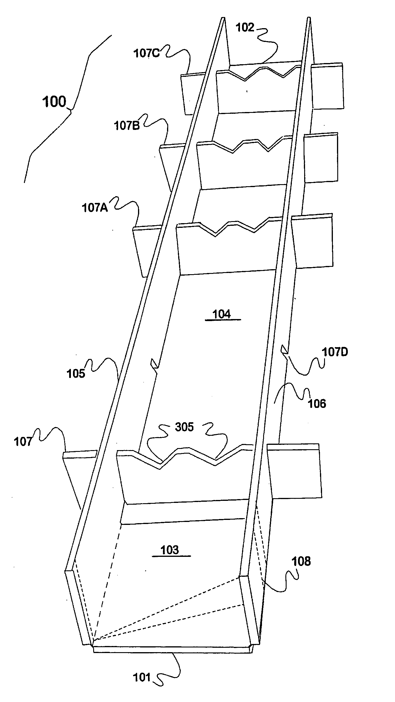
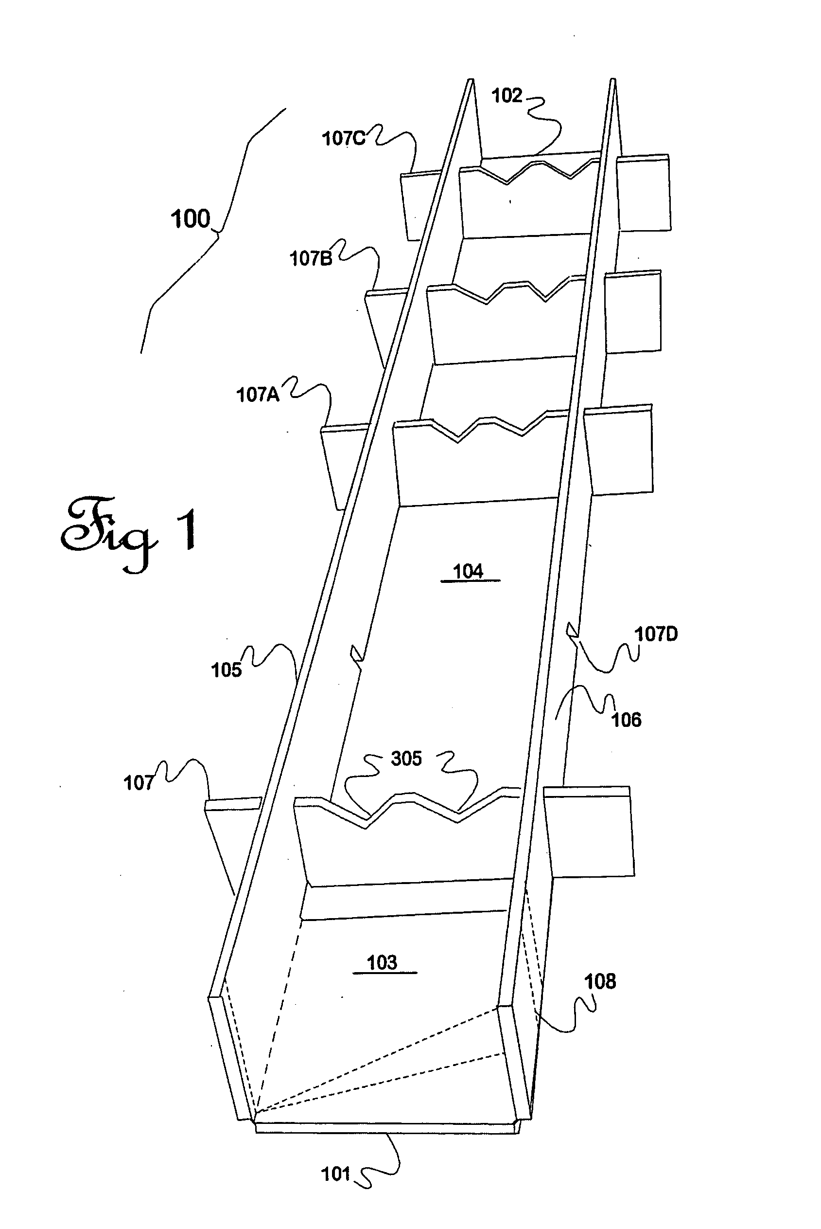
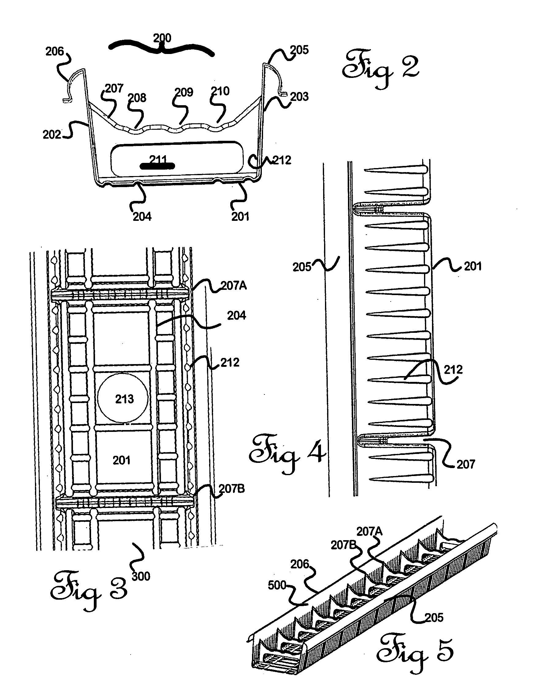
[0078]The principle of this invention—that of providing pre-formed, mainly sacrificial types of formwork for creation of landscape edging—is maintained through a number of examples which teach the invention in different embodiments. The inventors assume that the majority of demand for their invention will comprise guiding units that are either about 140 mm wide, or 250 mm wide, (that is, space between walls 105 and 106 of FIG. 1) to be used by landscapers or private persons when dividing an area into portions serving different purposes such as lawns or gardens. (It is important to note that those sizes are given by way of example only. The above dimensions are selected only as being suitable for use as a base for walls using standard brick sizes. There are of course many other possible convenient dimensions, depending for example on the primary objective of the edging which may for example be as a concealed way to carry water, electricity or communications about an area, or a barrie...
example 2
[0085]The invention has proceeded towards establishing suitable constructional materials that are economical to produce yet are sufficiently strong to withstand forces imposed during construction. Wooden or metal materials may be considered but carry significant cost and fabrication penalties. It is useful to consider other manufacturing options, particularly those employing other kinds of plastics material that are formed into shapes visually or functionally similar to those outlined in Example 1 by methods known to those skilled in the art, some of which are reviewed here.
[0086]Vacuum forming (also called thermoforming). This method of shaping flat sheets of a thermoplastics material appears to be particularly suited to the present invention. The descriptive name also includes pressure forming, and generally comprises the forcing by gas pressure (that is, including use of a vacuum inside the mould or gas pressure applied from outside, or both) of an originally flat sheet while hot...
example 3
[0102]An alternative plastics material is similar to a moulded flexible drainage pipe made for example of a black-coloured polyethylene or polyvinyl chloride plastics material, of circular cross-section having a corrugated or bellows-like wall along substantially the entire length. One example is sold in New Zealand under the brand “NOVAFLOW”. This material comprises a series of circular rings or a continuous spiral all joined sideways to each other. The resulting pipe is relatively flexible, like a bellows, along its length although surprisingly rigid under radial compression and is widely used after burial in shallow trenches in the drainage of soil, where the pipe is provided with a plurality of slits in the wall for the admittance of surplus ground water. The range of dimensions proposed are similar to those described elsewhere in this specification. One advantage of this material is that the lengthways flexibility applies to both horizontal and vertical axes and hence a user ha...
PUM
 Abstract
Description
Claims
Application Information
 - R&D
- Intellectual Property
- Life Sciences
- Materials
- Tech Scout
- Unparalleled Data Quality
- Higher Quality Content
- 60% Fewer Hallucinations
Browse by: Latest US Patents, China's latest patents, Technical Efficacy Thesaurus, Application Domain, Technology Topic, Popular Technical Reports.
© 2025 PatSnap. All rights reserved.Legal|Privacy policy|Modern Slavery Act Transparency Statement|Sitemap|About US| Contact US: help@patsnap.com


