Fluid preheating

Inactive Publication Date: 2007-08-09
AGILENT TECH INC
View PDF6 Cites 15 Cited by
  • Summary
  • Abstract
  • Description
  • Claims
  • Application Information

AI Technical Summary

Benefits of technology

[0019] In a preferred embodiment, the heating system comprises a sample injection unit located between the main heating unit and the auxiliary heating unit, with the sample injection unit being adapted for injecting a fluid sample into the fluid passing through the heating system. In this embodiment,

Problems solved by technology

The heating unit is adapted to be operated at a first temperature and to provide a heat transfer between the heating unit and the fluid passing through the heating flow path, with the heat transfer not being sufficient for heating up the fluid passing through the heating flow path to the first temperature.
The heating unit is purposely designed such that

Method used


Image

  • Fluid preheating
  • Fluid preheating
  • Fluid preheating

Examples


Example

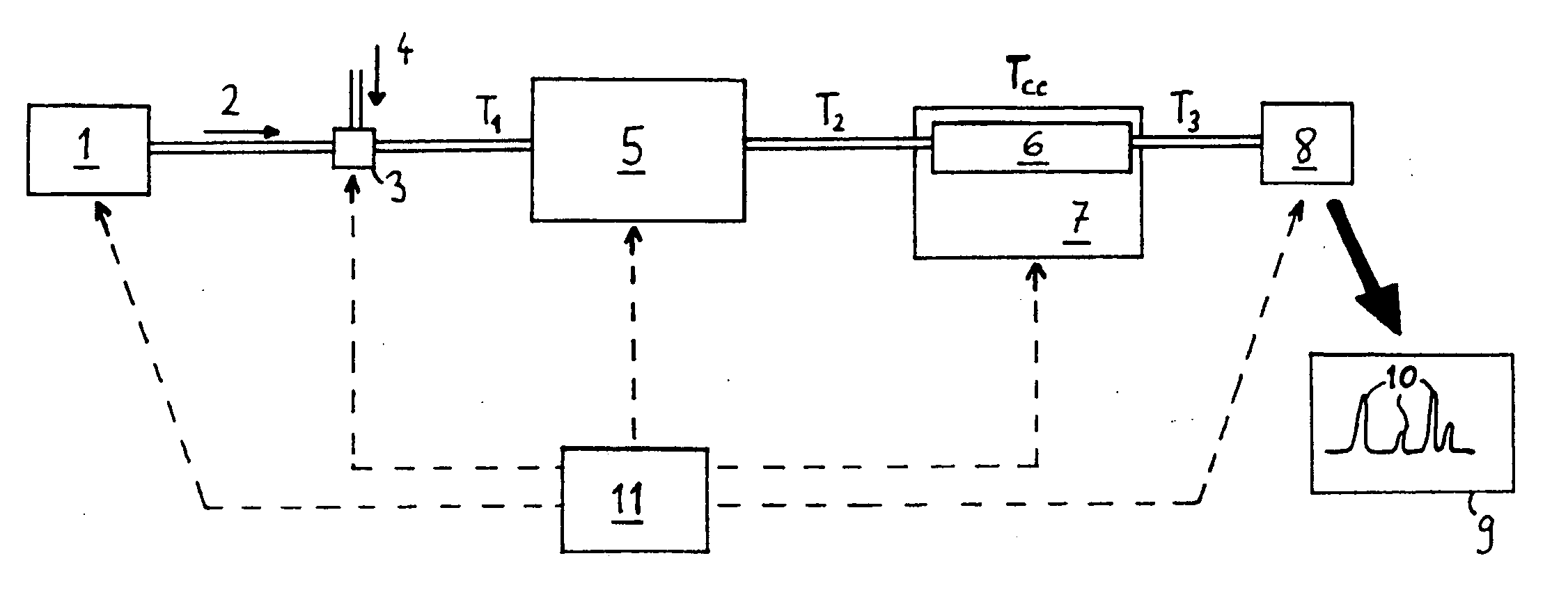
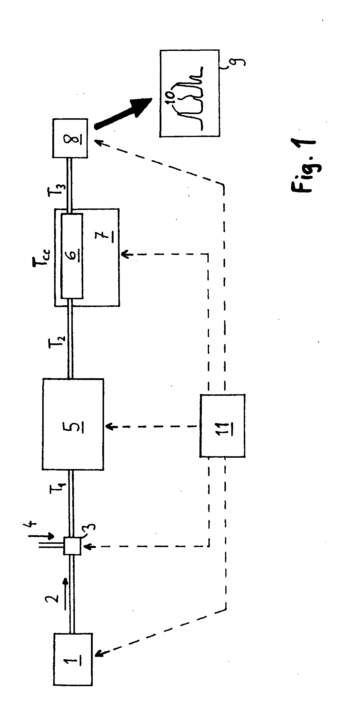
[0045]FIG. 1 gives an overview of a separation system adapted for separating compounds of a given sample. The separation system comprises a fluid delivery unit 1, e.g. a pump, for supplying a flow of eluent 2 to a sample injection unit 3. At the sample injection unit 3, a volume of fluid sample 4 may be injected. Both the eluent and the sample are supplied to a heating system 5. During the passage through the heating flow path of the heating system, the eluent and the sample are heated up. The eluent and the sample are supplied to a separation column 6 that is filled with a stationary phase. The separation system further comprises a thermostated column compartment 7 adapted for keeping the separation column 6 at a pre-defined temperature. The separation column 6 might e.g. be kept at a temperature of about 80° Celsius. Due to the interaction between the sample compounds and the packing material, the sample compounds appear at the separation column's outlet at different points of tim...


PUM


Abstract

A heating system for preheating a fluid. The heating system comprises a heating unit with a heating flow path; wherein the heating unit is adapted to be operated at a first temperature and to provide a heat transfer between the heating unit and the fluid passing through the heating flow path, with the heat transfer not being sufficient for heating up the fluid passing through the heating flow path to the first temperature.

Description

BACKGROUND ART [0001] 1. Field of the Invention [0002] The present invention relates to fluid preheating. [0003] 2. Discussion of the Background Art [0004] U.S. Pat. No. 5,238,557 describes an apparatus for controlling the temperature of a mobile phase in a fluid chromatographic system which comprises both an ingoing capillary connected to an inlet of a column and an outgoing capillary connected to an outlet of the column. A portion of the ingoing capillary and a portion of the outgoing capillary are arranged in thermal contact with each other to form a contact region wherein heat exchange can occur. In preferred embodiments, liquid leaving the column at an elevated temperature loses a portion of its heat, thus avoiding or at least substantially reducing the transfer of heat to the detector. At the same time, liquid flowing to the column is pre-heated by the liquid leaving the column so that the heating power required for bringing the mobile phase to the desired temperature is reduc...

Claims


Application Information

Patent Timeline
IPC IPC(8): F24D3/08
CPCG01N30/30
Inventor ZIEGLER, TONY
Owner AGILENT TECH INC
Why Eureka
Try Eureka