Laminated coil

Active Publication Date: 2007-08-09
MURATA MFG CO LTD
View PDF3 Cites 41 Cited by
  • Summary
  • Abstract
  • Description
  • Claims
  • Application Information

AI Technical Summary

Benefits of technology

[0016] According to the present invention, the coil conductors provided on the non-magnetic body section are provided on a main surface of the non-magnetic body section and inside the non-magnetic body section.
[0018] According to the present invention, a plurality of the non-magnetic body sections is provided inside the laminated body.
[0019] According to the structure according to the present invention, a plurality of the non-magnetic body sections is provided inside the laminated body. Thus, the amount of magnetic fluxes leaking from the non-magnetic body section to the outside of the laminated coil can be increased, and the DC superposition characteristic of the laminated coil can be improved.
[0020] The laminated coil according to the present invention includes a laminated body having magnetic body sections disposed on both main surfaces of a non-magnetic body section, the magnetic body sections each being formed by stacking a plurality of magnetic layers, the non-magnetic body section being formed by stacking a plurality of non-magnetic layers, and a coil including coil conductors provided on the magnetic body sections and the non-magnetic body section, the coil conductors being helically connected. Moreover, the coil number of the coil conductors provided on the non-magnetic body section is greater than the coil number of the coil conductors provided on layers other than the layers including the coil conductors provided on the non-magnetic body section. Thus, the amount of magnetic fluxes leaking from the non-magnetic body section to the outside of the laminated coil can be increased. In this way, a laminated coil that has an excellent DC superposition characteristic in which magnetic saturation is less likely to occur inside the laminated coil, the inductance value does not change even when a high electric current is applied can be obtained. Accordingly, the characteristics of the laminated coil as a choke coil can be improved.

Problems solved by technology

For a laminated coil having a closed magnetic path, there is a problem in that the desired choke coil characteristic cannot be obtained because the inductance value suddenly decreases when the current exceeds a predetermined value.
However, according to the structure of Patent Document 1, the amount of magnetic fluxes that leaks from the non-magnetic body layers is limited because the coil conductors provided on the non-magnetic body layers and the coil conductors provided on the ferromagnetic layers have the same shape and coil number.

Method used


Image

  • Laminated coil
  • Laminated coil
  • Laminated coil

Examples


first embodiment

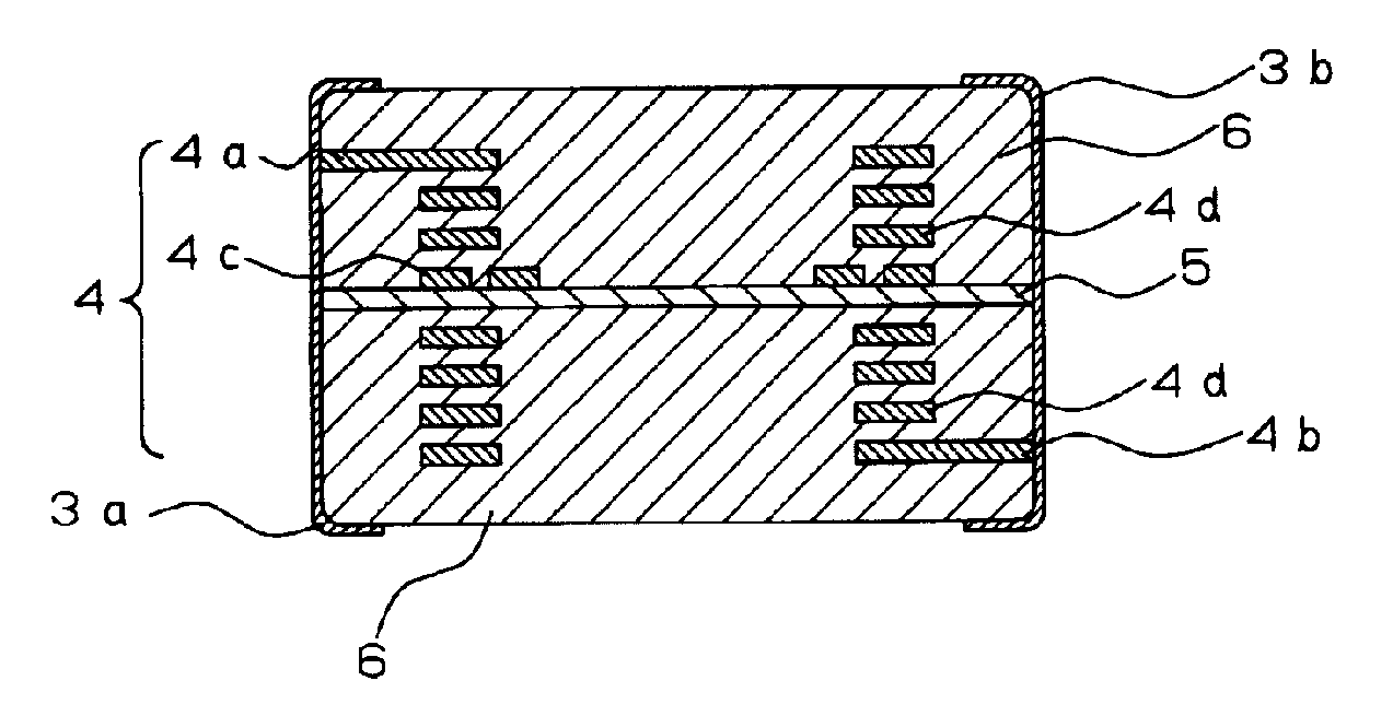
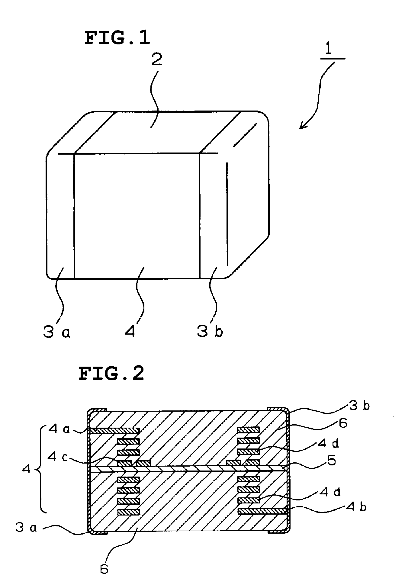
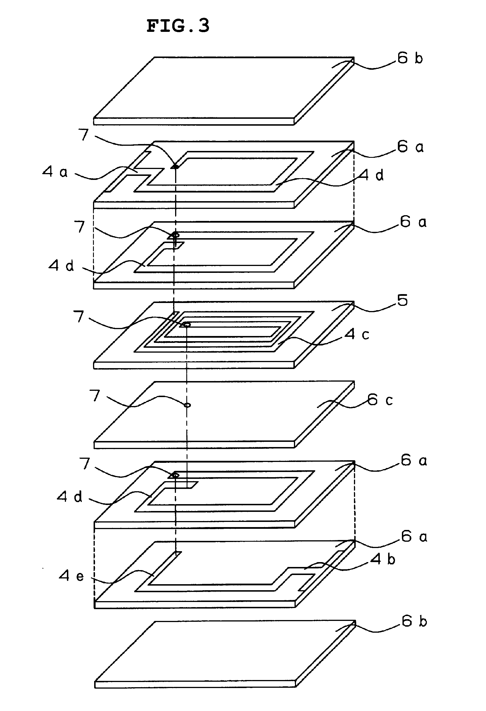
[0034]FIG. 1 is an external perspective view of a laminated coil according to a first embodiment of the present invention. FIG. 2 is a schematic cross-sectional view of the laminated coil. A laminated coil 1 includes a laminated body 2, external electrodes 3a and 3b provided on the surface of the laminated body 2 and coil conductors 4 embedded in the laminated body 2. The laminated body 2 is structured such that magnetic body sections 6 formed by stacking magnetic layers is disposed on both main surfaces of a non-magnetic body section. Inside the laminated body 2, the coil conductors 4 are embedded so as to formed one helical coil whose axial direction is the lamination direction.

[0035] The non-magnetic body section 5 and the magnetic body sections 6 are each constituted of at least one green sheet composed of non-magnetic material or magnetic material. A first end portion 4a of the coil conductors 4 is connected to the external electrode 3a and a second end portion 4b is connected...

second embodiment

[0045]FIGS. 4 and 5 illustrate a schematic sectional view and an exploded perspective view, respectively, of a laminated coil according to a second embodiment of the present invention. According to this embodiment, above and below a non-magnetic body section 13, coil conductors 12c, whose coil number is greater than that of coil conductors 12d provided on a magnetic body section 14, are provided. The laminated coil according to this embodiment, similar to the laminated coil according to the first embodiment, is produced through steps of stacking ferrite green sheets including coil conductors in the order shown in FIG. 5, pressure compressing, dicing the sheets into chips, and, then, forming external terminal electrodes.

[0046] As shown in FIG. 5, by increasing the coil number of the coil conductors 12c that are provided above and below the non-magnetic body section 13, the magnetic field leaking outside the laminated coil can be increased more than that of the first embodiment. Thus...

third embodiment

[0047]FIG. 6 illustrates a schematic cross-sectional view of a laminated coil according to a third embodiment of the present invention. According to this embodiment, coil conductors 22c provided above and below a non-magnetic layer 23 each have a coil number of three turns, and coil conductors 22d provided above and below the coil conductors 22c each have a coil number of two turns. By employing a laminated coil having a structure according to this embodiment, the magnetic field can be concentrated more at the vicinity of the non-magnetic layer 23. Thus, the magnetic saturation inside the laminated coil is reduced, and the DC superimposition characteristic of the laminated coil can be improved.

[0048]FIG. 7 illustrates the DC superimposition characteristic of the laminated coil according to this embodiment. FIG. 7 illustrates a characteristic 25 for a case in which the coil number of the coil conductors 22c and the coil conductors 22d is greater than that of another coil conductor 2...


PUM


Abstract

A laminated coil includes a non-magnetic body section inside a laminated body. On the non-magnetic body section, a coil conductor is provided. The number of coil turns of the coil conductor is greater than the number of coil turns of a coil conductor other than the coil conductor on the non-magnetic body section.

Description

TECHNICAL FIELD [0001] The present invention relates to a laminated coil and, more specifically, relates to a laminated coil having an excellent direct current (DC) superimposition characteristic. BACKGROUND ART [0002] A laminated coil is produced by stacking magnetic sheets each composed of ferrite or the like and provided with a coil conductor consisting primarily of Ag. Such a laminated coil is used in various circuits. The laminated coil is characteristic in that effective magnetic permeability is increased and a high inductance value is obtained because a closed magnetic path is formed by the magnetic field that is generated by an electrical current flowing through the coil conductors. The laminated coil is also advantageous in that loss due to the conductor resistance is small because the conductor patterns primarily consist of Ag. Thus, the laminated coil is used as a choke coil for a switching power supply to which a high current is applied. [0003] For coil elements, the rel...

Claims


Application Information

Patent Timeline
IPC IPC(8): H01F5/00H01F3/14H01F17/00H01F27/24H01F37/00
CPCH01F3/14H01F37/00H01F17/0006
Inventor TSUZUKI, KEIICHIMIZUNO, TATSUYA
Owner MURATA MFG CO LTD
Why Eureka
Try Eureka