Battery backed service indicator aids for field maintenance

a technology of service indicator and battery, applied in the field of service indicators, can solve the problems of inability to assist the technician, compromise the use of diagnostic indicators to direct maintenance actions, etc., and achieve the effect of preserving the functionality of the diagnostic indicator

Inactive Publication Date: 2007-08-09
IBM CORP
View PDF17 Cites 4 Cited by
  • Summary
  • Abstract
  • Description
  • Claims
  • Application Information

AI Technical Summary

Benefits of technology

[0005] The present invention addresses the above and other issues by providing a technique that allows a diagnostic indicator to be powered from an alternative, independent power source when normal system power is removed from a component, thereby preserving the use of the diagnostic indicator to complete a maintenance task.
[0006] Specifically, dual power sources are provided for the diagnostic indicator. The primary source is the normal system power of the device in which the component is installed. Typically, this power source is based on AC power from an electrical outlet. The AC input power source can be conditioned to become DC power used by the internal circuitry and control functions. An alternate source is a self-contained power source such as a battery that can be located within or on the component itself. By using the device's power source as the primary power source, the life of the alternate power source is preserved. Moreover, when the component needs to be removed from the device and, therefore, from the primary power source, the state of the diagnostic indicator is latched and shifted to the alternate power source, thereby preserving the functionality of the diagnostic indicator.

Problems solved by technology

However, for devices that have packaging concepts that require component assemblies to be removed from a chassis and therefore an associated electrical power source, the use of the diagnostic indicators to direct maintenance actions is compromised.
In such situations, when the diagnostic indicator is no longer powered, it cannot aid the technician at a time when it is most needed.

Method used


Image

  • Battery backed service indicator aids for field maintenance
  • Battery backed service indicator aids for field maintenance
  • Battery backed service indicator aids for field maintenance

Examples


Embodiment Construction

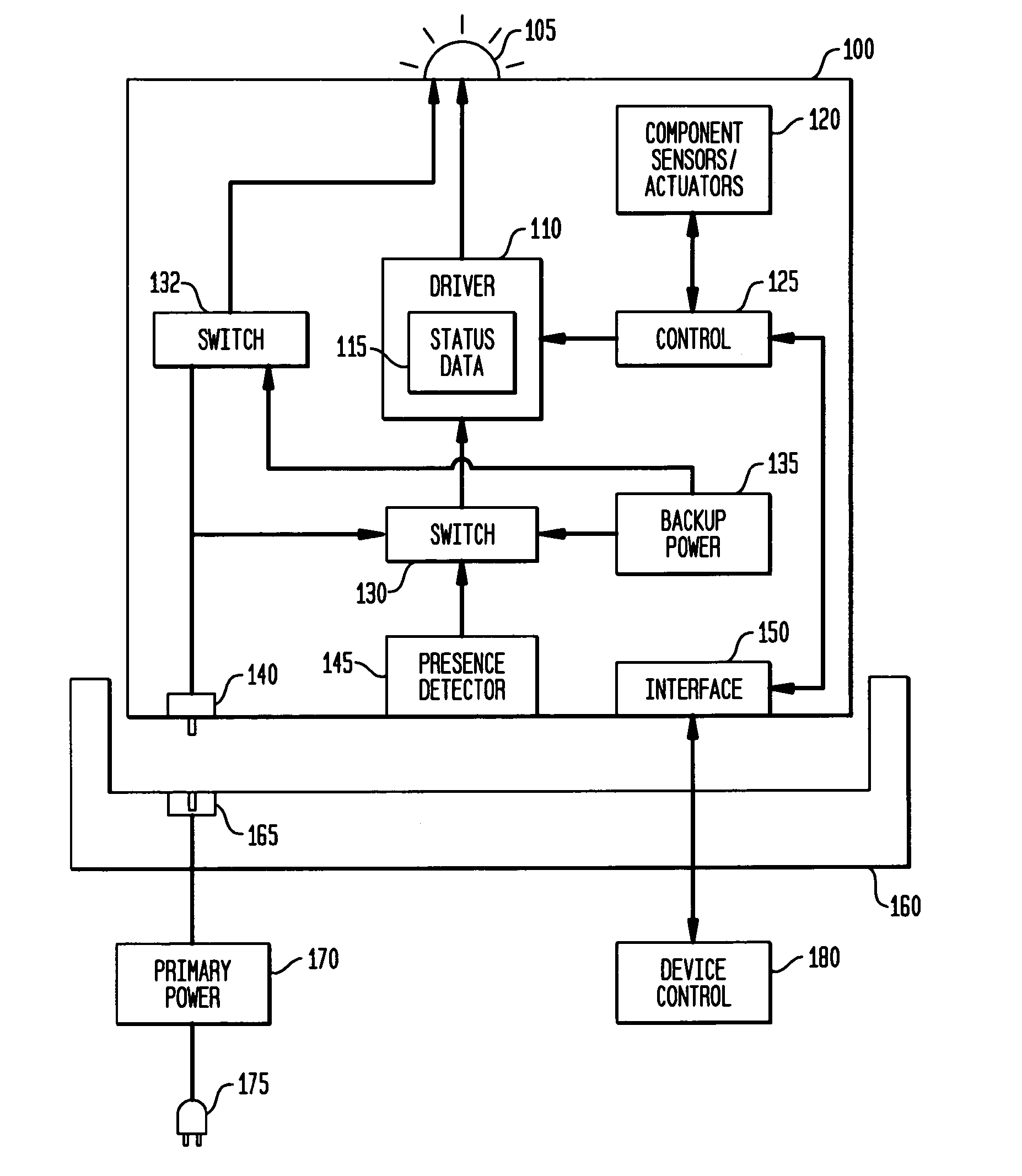
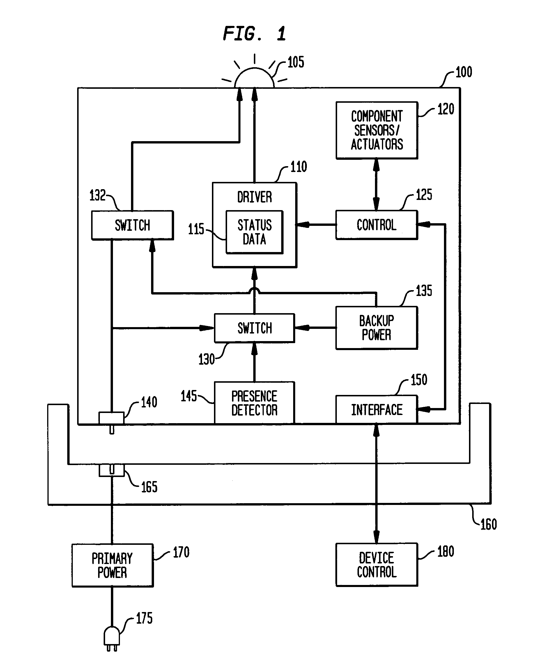
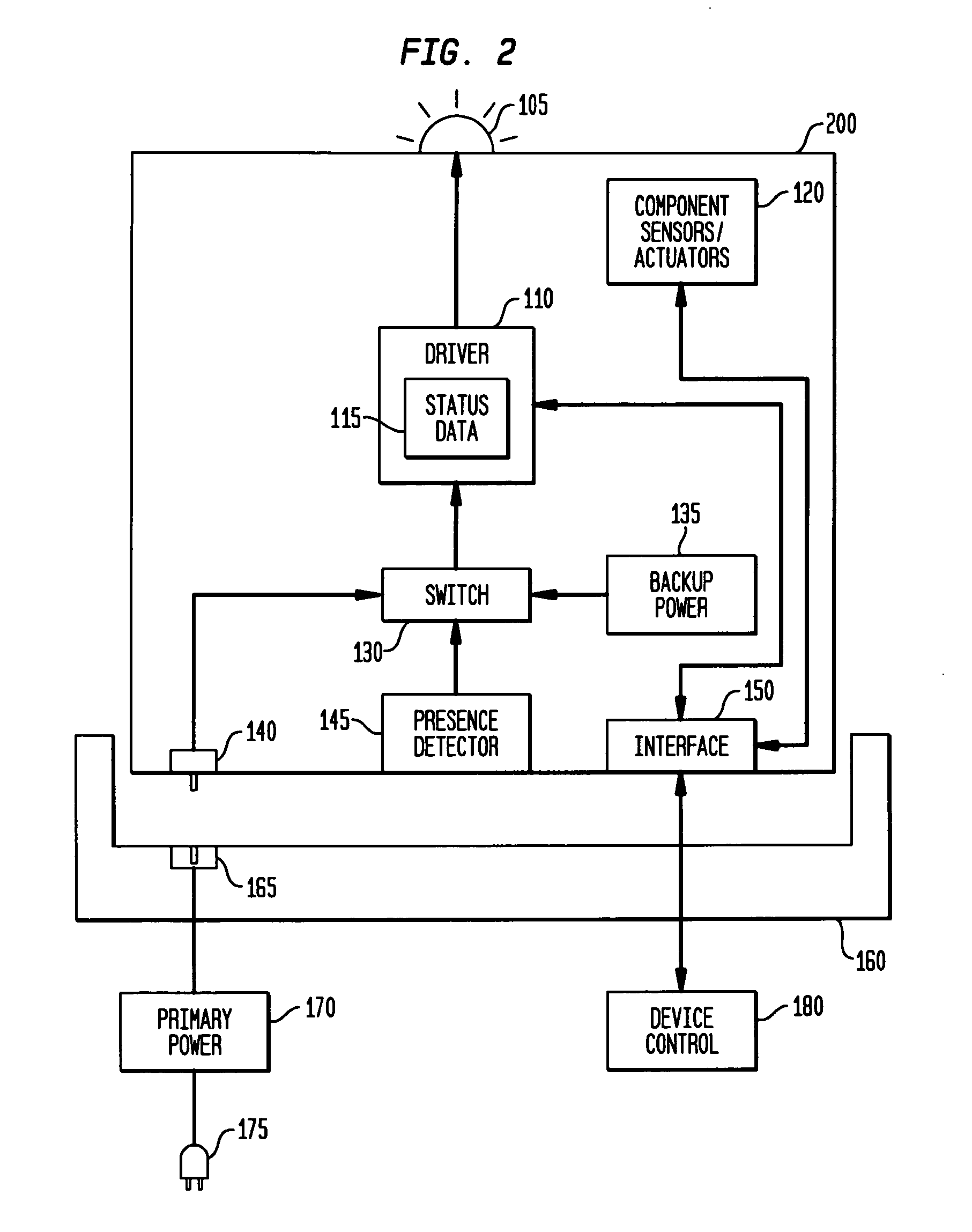
[0025] In a system that uses diagnostic indicators to assist in maintenance identification of components, the invention provides an alternate power source and a means of latching the indicator state that is powered from the alternate power source. When a maintenance activity that will remove the normal power source from the diagnostic indicator is required, the system places the indicator into a state that is required for the service activity and transfers the latched state and power source for the indicator to the alternate source. This can be done either manually by the technician, such as by moving a switch, or automatically, such as upon removal of normal power to the indicator. The state of the indicators is maintained and the service activity can continue to exploit the diagnostic indicators with the higher-level assembly removed from the enclosure / chassis.

[0026] As indicated, various electrically powered devices have packaging concepts that require component assemblies to be...


PUM


Abstract

A self-contained backup power source such as a battery is provided for components within an electrically powered device such as a storage controller, photocopier or the like, to maintain diagnostic status data and to power a service indicator aid, or diagnostic indicator, such as an LED. A switch selects the backup power source when a primary power source of the electrically powered device is no longer available to the component, such as when the component is removed from the electrically powered device, the primary power source is disconnected as a safety precaution when servicing or replacing the component, or a higher-level assembly, in which the component is provided, is removed from the electrically powered device. The diagnostic indicator may be powered separately from the data storage device.

Description

RELATED APPLICATIONS [0001] This application is a continuation application of U.S. Ser. No. 10 / 976,202, filed Oct. 27, 2004.FIELD OF THE INVENTION [0002] The invention relates generally to the field of service indicators such as diagnostic LEDs that are used to display information regarding a component of an electrically powered device such as a computer storage system, photocopier or the like, and, more specifically, to a way of providing backup power so that the service indicator continues to be active even when power is removed from the component. DESCRIPTION OF THE RELATED ART [0003] Various electrically powered devices such as computer systems, storage controllers, photocopiers and many others have a diagnostic functionality to indicate when servicing or replacement of their components is needed. Diagnostic control logic may process signals from sensors and actuators of the components to determine when a component is not performing properly or otherwise requires servicing, for ...

Claims


Application Information

Patent Timeline
Patent Type & Authority Applications(United States)
IPC IPC(8): G08B29/00
CPCH02J9/06G06F1/30G06F1/26G06F11/32
Inventor JONES, CARL E.KUBO, ROBERT A.WALLS, ANDREW D.
Owner IBM CORP
Why Eureka
Try Eureka