
Remote body arrays for high-performance magnetic resonance imaging and spectroscopy

Active Publication Date: 2010-08-26
NEW YORK UNIVERSITY +1
View PDF6 Cites 23 Cited by
  • Summary
  • Abstract
  • Description
  • Claims
  • Application Information

AI Technical Summary

Benefits of technology

[0008]An object of the present invention is to make use of large encircling integrated arrays to gain the benefits of SNR and parallelism described above while eliminating the ergonomic and other practical challenges associated with many-element surface coil arrays.
[0009]The above object is achieved in accordance with the invention by replacing or augmenting the functions of a traditional body coil and separately configured receive arrays in MR scanners with an integrated many-element array at a distance from the body (e.g. lining or incorporated into the scanner bore). This enables broad functionality, including volumetric imaging with high signal-to-noise ratio (SNR) and highly parallel transmission and reception, all with a dramatically improved workflow. For routine examinations using such a system, no custom coils need to be placed on a patient, no coils or cables are visible to patient or operator, and coil array calibrations are facilitated by the fixed position of array elements. At the same time, the functionality of conventional body coils and surface coil arrays is preserved using appropriate combinations of elements of the remote body array.

Problems solved by technology

Such large arrays are associated with various practical challenges, including increased bulk, cost, and complexity as compared with few-element designs.
Patient-specific placement of heavy many-element arrays with dense cabling can be cumbersome, and the ability to accommodate multiple body types can be sacrificed.
The use of multiple many-element arrays targeted to different body habitus or body region could also add significant expense to MR systems.
Flexible many-element designs present challenges for accurate coil sensitivity calibration, since coil deformation can perturb dramatically the sensitivity of small elements.
Rigid contoured designs, on the other hand, tend to accommodate only a small range of possible body types (and split designs may still suffer from some degree of motion-related sensitivity shifts).
All surrounding many-element designs, furthermore, tend to fill large quantities of valuable space within the scanner bore, thereby limiting the size of subjects who may be scanned.
It is known that a coil's sensitivity is generally attenuated and broadened with increasing distance from the coil, and broad sensitivities are known to result in significant noise amplification in parallel imaging.

Method used


Image

  • Remote body arrays for high-performance magnetic resonance imaging and spectroscopy
  • Remote body arrays for high-performance magnetic resonance imaging and spectroscopy
  • Remote body arrays for high-performance magnetic resonance imaging and spectroscopy

Examples


Embodiment Construction

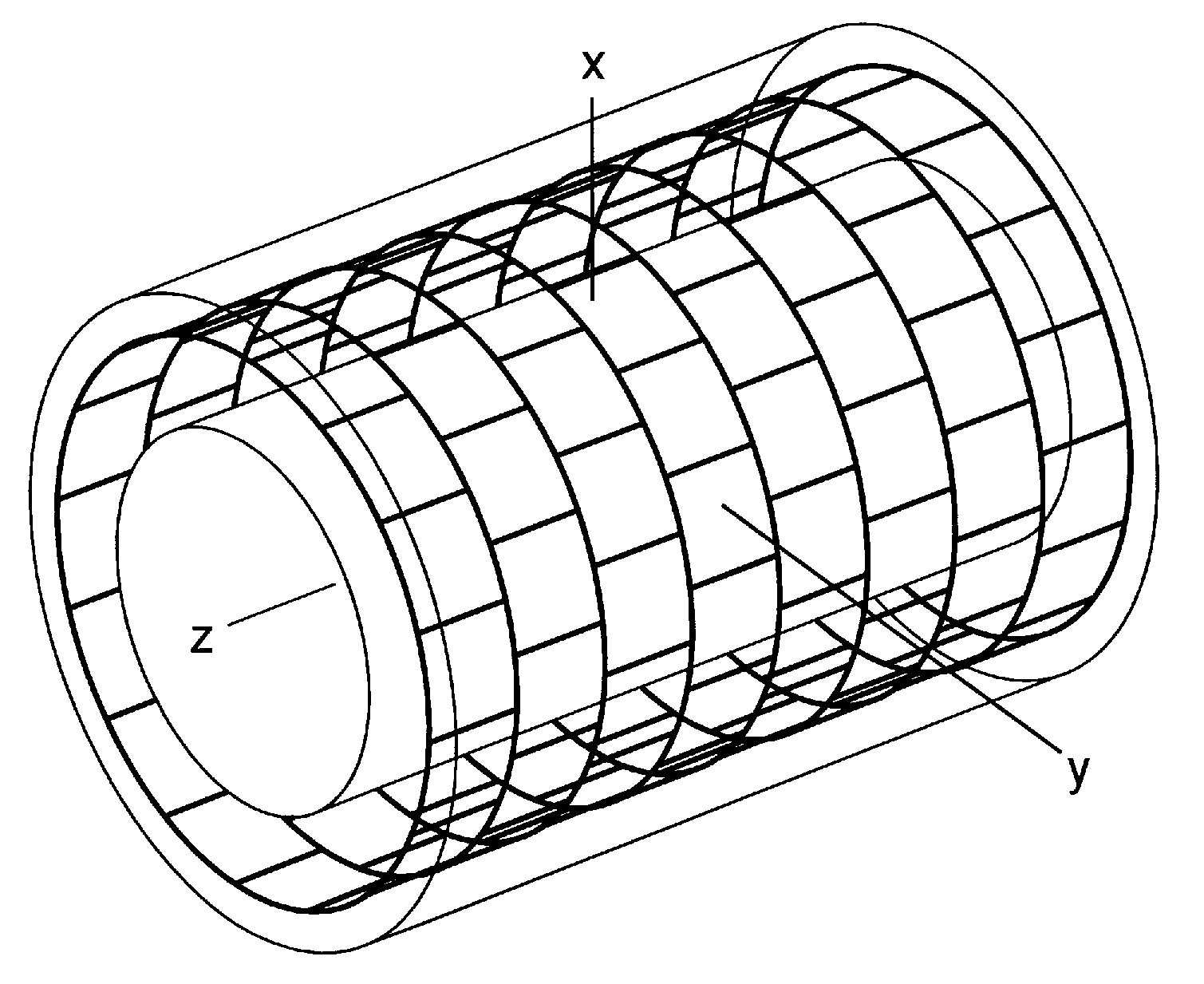
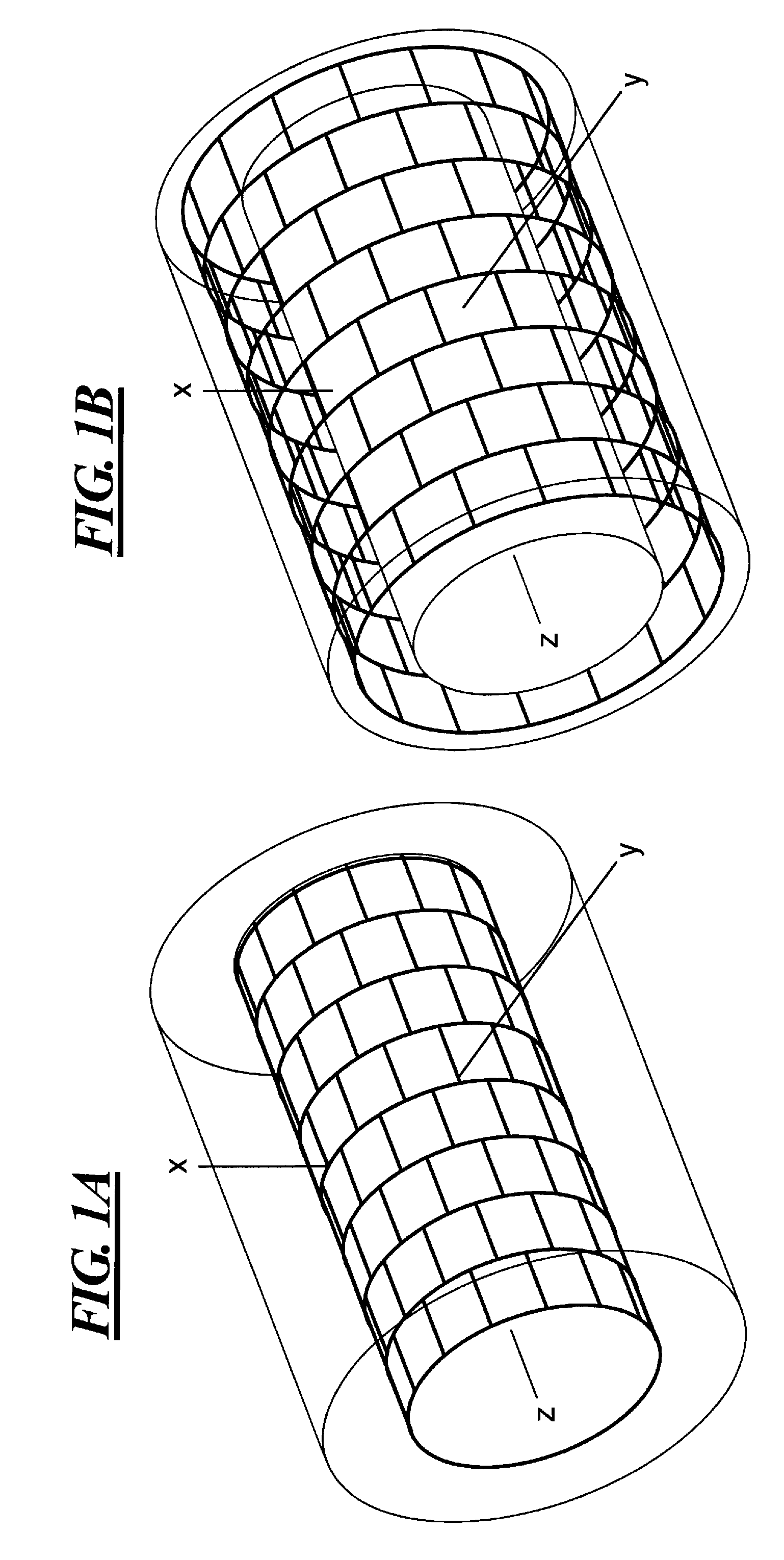
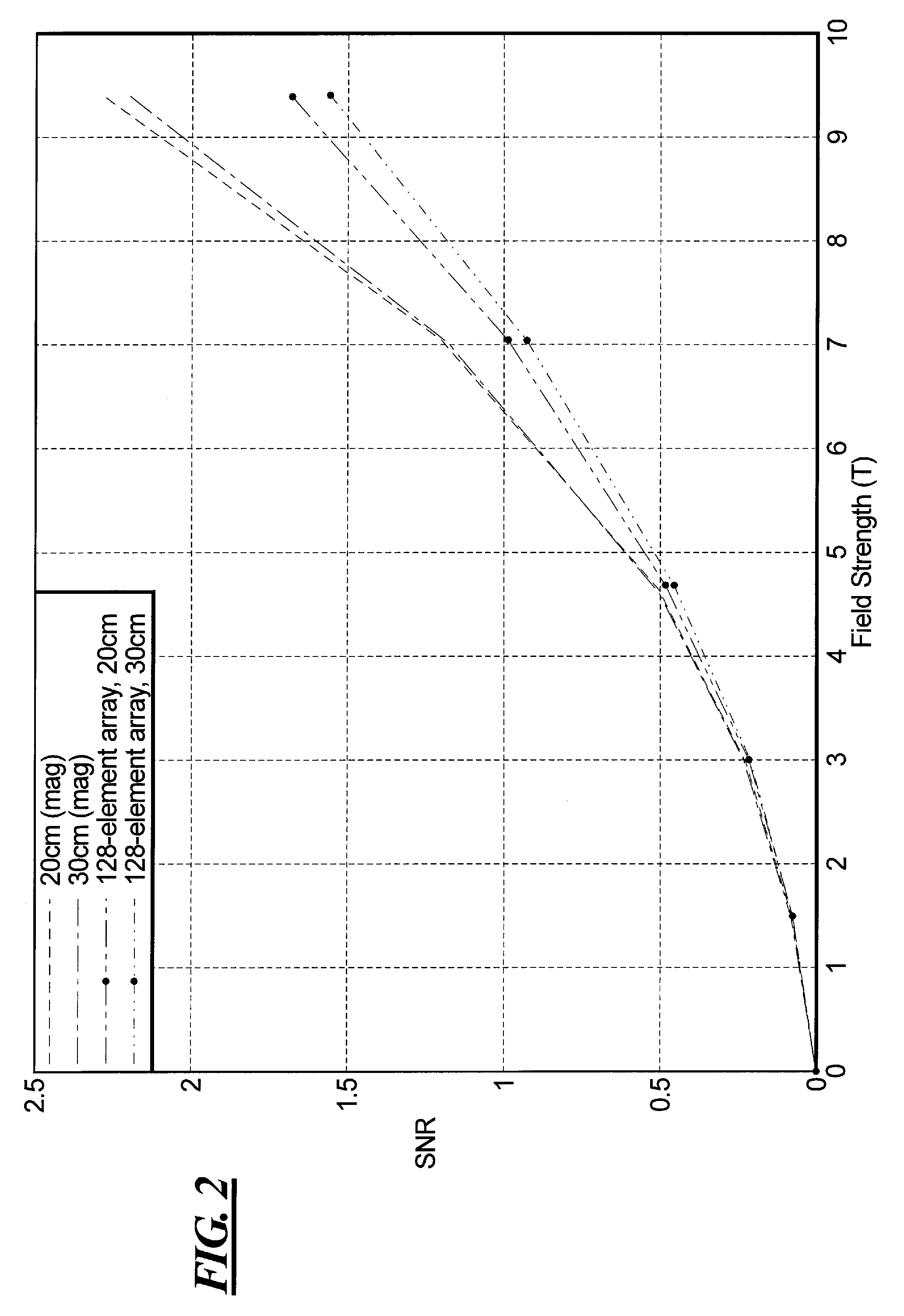
[0018]in order to explore the behavior of SNR as a function of distance from the body, numerical simulations were performed, using the general methodology described in (Schnell W, Renz W, Vester M, Ermert H. Ultimate Signal-to-Noise Ratio of Surface and Body Antennas for Magnetic Resonance Imaging. IEEE Transactions on Antennas and Propagation 2000; 48(3): 418-428) updated as outlined in (Sodickson D K, et. al. Approaching the Ultimate Intrinsic Signal-to-Noise Ratio in a Cylindrical Geometry; Electrodynamics of Large Encircling Radiofrequency Coil Arrays. 2008; in preparation). FIG. 1A shows the geometry of the simulations, in which a dielectric cylinder (body liner) of 20 cm radius with uniform electrical permittivity and conductivity (approximating the average frequency-dependent properties of muscle tissue in this case) is surrounded by a cylindrical surface of equal or greater radius on which currents are allowed to flow. FIG. 1B shows the same geometry for an array with a radi...


PUM


Abstract

In a magnetic resonance imaging apparatus and method, radio frequency signals are radiated into an examination subject and / or received from the examination subject by an array of radio frequency coils that completely encircles the examination subject, and that is located at a distance from the examination subject out of contact with the examination subject.

Description

BACKGROUND OF THE INVENTION[0001]1. Field of the Invention[0002]The present invention relates to the use and configuration of radio frequency transmitting and / or receiving coils in magnetic resonance imaging.[0003]2. Description of the Prior Art[0004]The body coil incorporated into the bore of most modern MR scanners is typically a birdcage design operated as a single quadrature element. At low to moderate magnetic field strengths, this design allows more or less homogeneous excitation and reception. Increased SNR in reception may be achieved through the use of radiofrequency (RF) coil arrays (Roemer P B, Edelstein W A, Hayes C E, Souza S P, Mueller O M. The NMR phased array. Magn Reson Med 1990; 16(2): 192-225).Over the past decade, the use of radiofrequency coil arrays in MRI has increased dramatically. Benefits of many-element arrays include both SNR improvements (Roemer P B, Edelstein W A, Hayes C E, Souza S P, Mueller O M. The NMR phased array. Magn Reson Med 1990; 16(2): 192-2...

Claims


Application Information

Patent Timeline
IPC IPC(8): G01R33/48
CPCG01R33/3415G01R33/34023
Inventor SODICKSON, DANIELBIBER, STEPHANVESTER, MARKUSRENZ, WOLFGANGSCHNELL, WILFRIED
Owner NEW YORK UNIVERSITY
Learn More