Electronic article surveillance tag having an expulsion detrimental substance system with substance routing system

a technology of electronic articles and surveillance tags, applied in the field of security tags, can solve the problems of increasing the likelihood, easy to be cut and damaged, and easily separated from each other, and achieve the effect of reducing the likelihood of being re-used, increasing the likelihood, and increasing the likelihood

Active Publication Date: 2007-08-09
SENSORMATIC ELECTRONICS CORP
View PDF28 Cites 19 Cited by
  • Summary
  • Abstract
  • Description
  • Claims
  • Application Information

AI Technical Summary

Problems solved by technology

This locks the tack and the tag body, forming or securing the EAS tag to the article so that the tag and article cannot be readily separated from each other.
Such materials, however, are susceptible to being cut and damaged.
This tends to be a disadvantage, since it increases the likelihood that the locking feature of the tag can be separated from the EAS sensor part of the tag or can be exposed and defeated.
This likewise tends to be a disadvantage, since use of large tags detracts from the aesthetic appearance of the articles to which the tags are attached.
As a result, unauthorized removal of the compa

Method used


Image

  • Electronic article surveillance tag having an expulsion detrimental substance system with substance routing system
  • Electronic article surveillance tag having an expulsion detrimental substance system with substance routing system
  • Electronic article surveillance tag having an expulsion detrimental substance system with substance routing system

Examples


Embodiment Construction

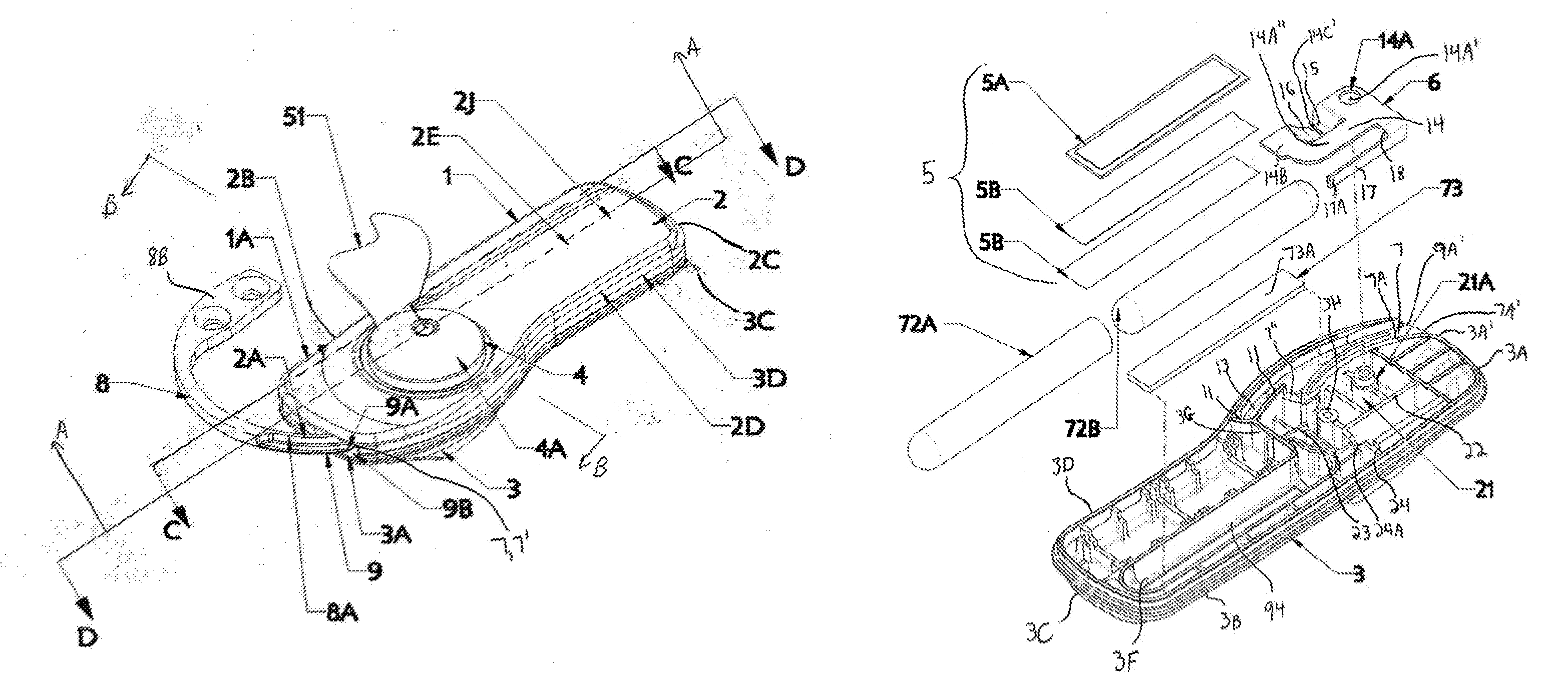
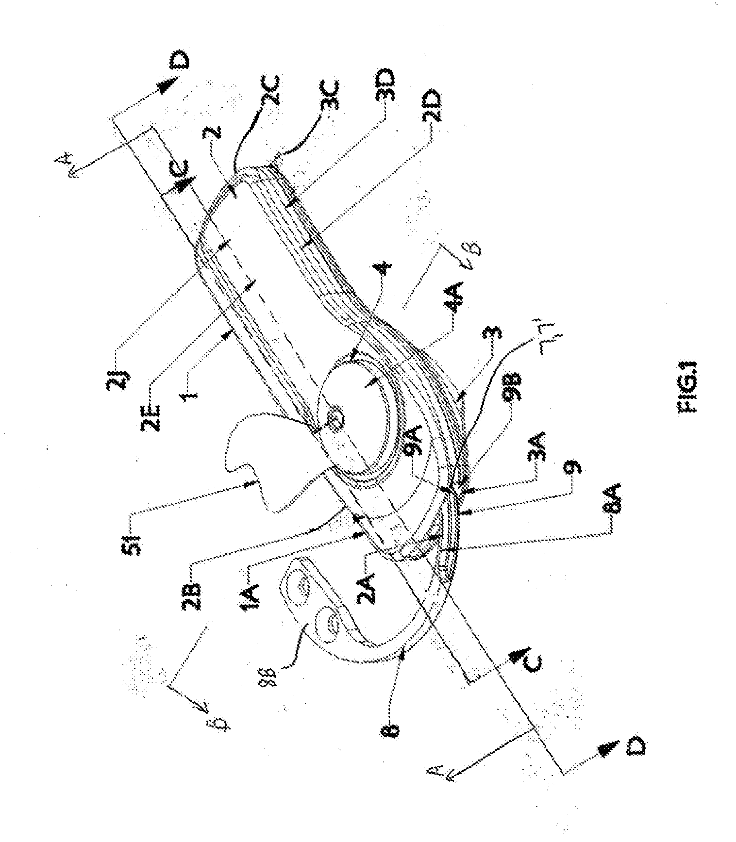
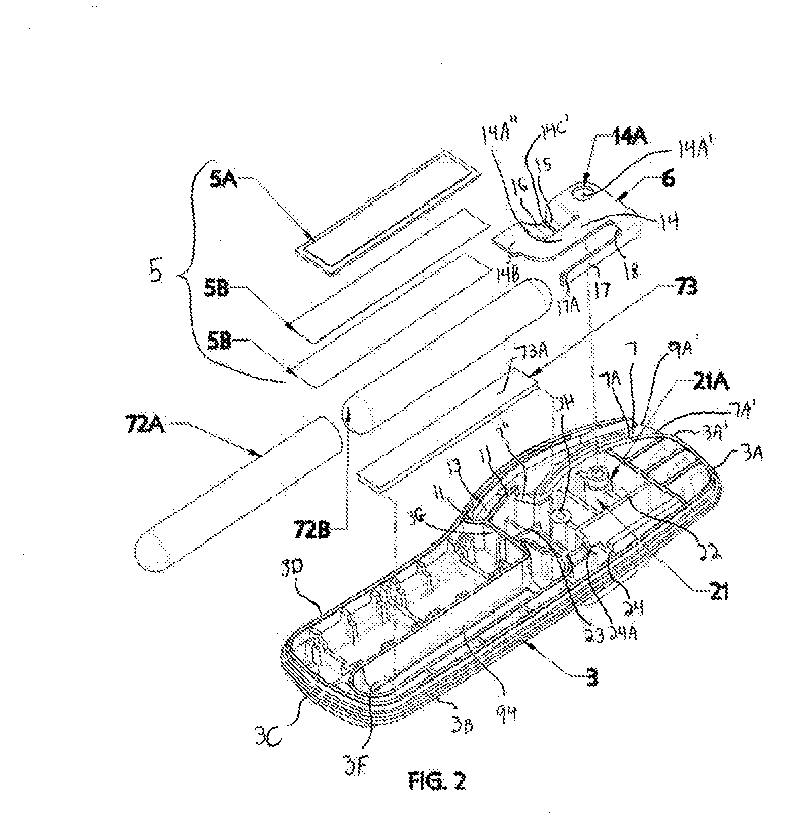
[0043]Embodiments may be directed to apparatuses, systems and methods including, in accordance with the principles of the invention, an EAS tag comprising a tag body and an attaching assembly for attaching the tag body to an article. The attaching assembly may include a tack assembly or other part, which is receivable in the tag body, and the tag body may be provided with a spring clamp or other preventing mechanism for releasably preventing withdrawal of the attaching assembly part. A channel defining structure within the tag body may define an arcuate channel. This channel may lead to the preventing mechanism and may permit an arcuate probe to be guided to the preventing mechanism for releasing same. Release of the preventing mechanism may permit withdrawal of the attaching assembly part, thereby separating the attaching assembly and article from the tag body. An abutment within the arcuate channel may prevent the insertion of a relatively rigid wire, formed substantially in the a...


PUM


Abstract

An EAS/EXPULSION DETRIMENTAL SUBTANCE tag in which the tag is held to an article by an attaching assembly, a part of which may be releasably prevented from being withdrawn from the body of the tag. The tag body may be provided with an arcuate channel through which an arcuate detacher probe can be guided for releasing the attaching assembly part. A spring clamp may provide the releasable preventing function and may include jaws specifically adapted to respond to in-plane torsional and/or other forces provided by the arcuate probe, which may be moved through the arcuate channel by rotation to reach the spring clamp. An abutment may be placed within the arcuate channel to prevent a relatively rigid wire formed into an arcuate shape from being used to release the attaching assembly part. The Benefit Denial (Ink portion) of this tag may feature an ink vial that may be disposed inside of a rubber bladder, which may then be placed in a completely sealed, ultrasonically welded compartment. In one embodiment, when the tag and its ink vial are attacked, the tag will expel the detrimental substance out and onto the article being protected. In another embodiment, when the tag is attacked, the detrimental substance may be forced out of the bladder and then into a channel and then out a hole in the rampart area and may stain the article that is being protected.

Description

[0001]This application claims priority to the U.S. Provisional Patent Application Ser. No. 60 / 771,410 titled “Electronic Article Surveillance Tag Having Detrimental Sub[s]tance Expulsion System with Breakable Vial” filed Feb. 7, 2006, and to the U.S. Provisional Patent Application Ser. No. 60 / 771,411 titled “Electronic Article Surveillance Tag Having an Expulsion Detrimental Sub[s]tance System with Substance Routing System” filed Feb. 7, 2006, both of which are incorporated herein by reference in their entirety.CROSS REFERENCES TO RELATED APPLICATIONS[0002]This application is related to the following application, which is being filed concurrently herewith and is incorporated by reference in its entirety:[0003]“Electronic Article Surveillance Tag Having a Detrimental Substance Expulsion System With Breakable Vial.”STATEMENT REGARDING FEDERALLY SPONSORED RESEARCH[0004]Not Applicable.BACKGROUND OF THE INVENTION[0005]1. Field of the Invention[0006]This invention relates generally to sec...

Claims


Application Information

Patent Timeline
IPC IPC(8): G08B13/14
CPCE05B39/002E05B73/0017G08B15/02G08B13/2448G08B13/2434Y10T70/5004
Inventor LYNCE, JOHN L.VALADE, FRANKLIN H.CWIK, KRYSTYNA E.SZKLANY, CRAIG R.
Owner SENSORMATIC ELECTRONICS CORP
Why Eureka
Try Eureka