
Transflective liquid crystal display devices and fabrication methods thereof

a liquid crystal display and reflector technology, applied in non-linear optics, instruments, optics, etc., can solve the problems of deteriorating lcd performance, high production cost, and complex lithography process, and achieve balanced brightness and contrast ratio

Inactive Publication Date: 2007-08-09
IND TECH RES INST
View PDF6 Cites 17 Cited by
  • Summary
  • Abstract
  • Description
  • Claims
  • Application Information

AI Technical Summary

Benefits of technology

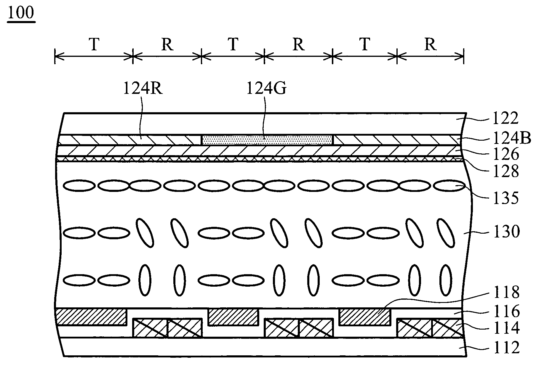
[0011]Accordingly, a transflective liquid crystal display device with a reflector structure is provided. A step is created between a transmissive region and a reflective region, causing a recess formed on the transmissive region. Different alignment layers, separately formed on the transmissive and reflective regions, provide both regions with balanced brightness and contrast ratio.

Problems solved by technology

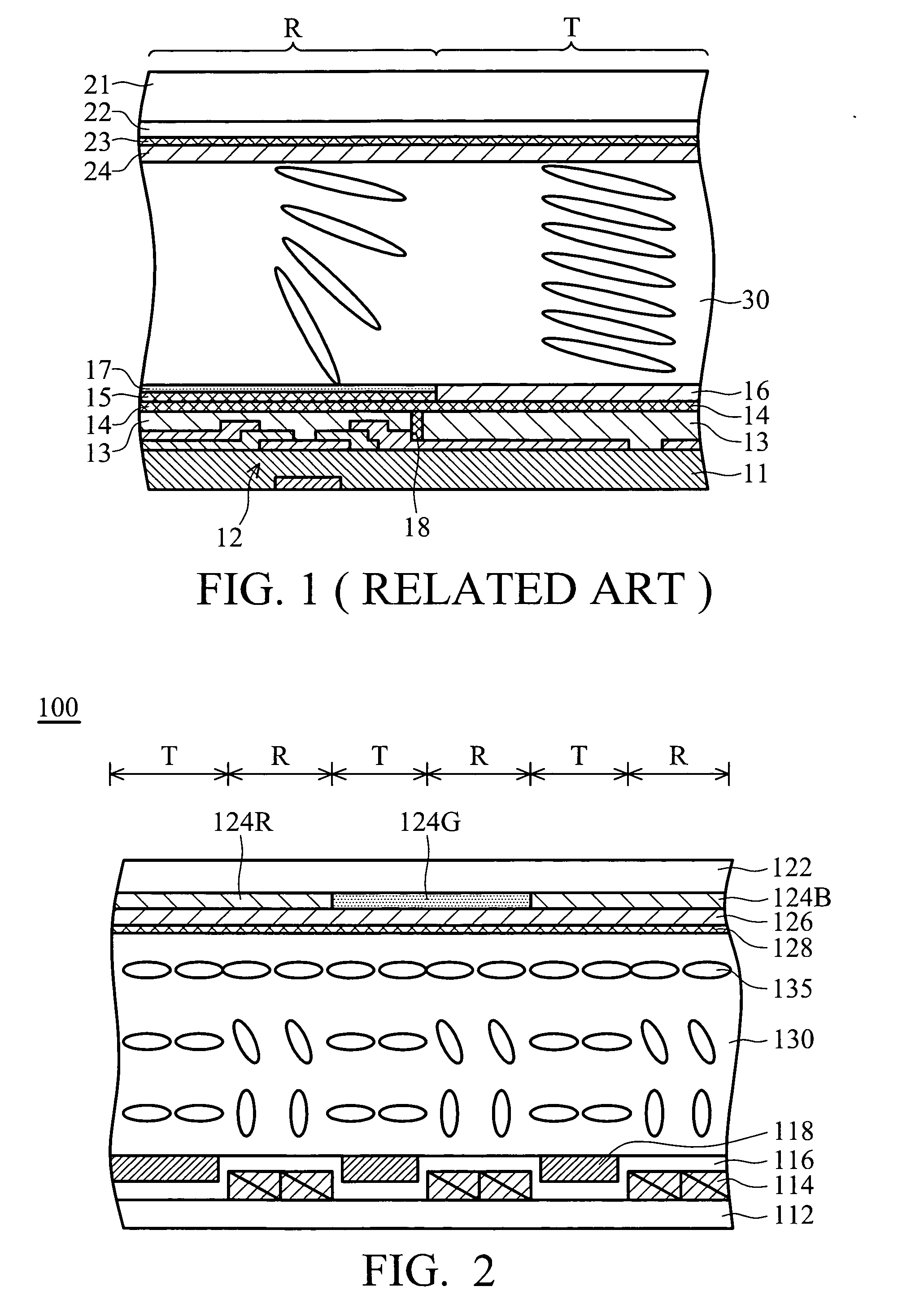
The distance of light travel of the reflective region is twice as long as the distance of light travel of the transmissive region; however, the cell gap in the reflective region must differ from the cell gap in the transmissive region, resulting in deteriorating LCD performance, such as variations in brightness and color.
Forming different alignment layers on the reflective region R and the transmissive region T respectively, however, requires intricate lithography processes.
The conventional method requires the tedious addition of photo-catalyst in PI alignment layer and photo mask procedures, causing high production cost and low yield.

Method used


Image

  • Transflective liquid crystal display devices and fabrication methods thereof
  • Transflective liquid crystal display devices and fabrication methods thereof
  • Transflective liquid crystal display devices and fabrication methods thereof

Examples


Embodiment Construction

[0022]The following description is of the best-contemplated mode of carrying out the invention. This description is made for the purpose of illustrating the general principles of the invention and should not be taken in a limiting sense. The scope of the invention is best determined by reference to the appended claims.

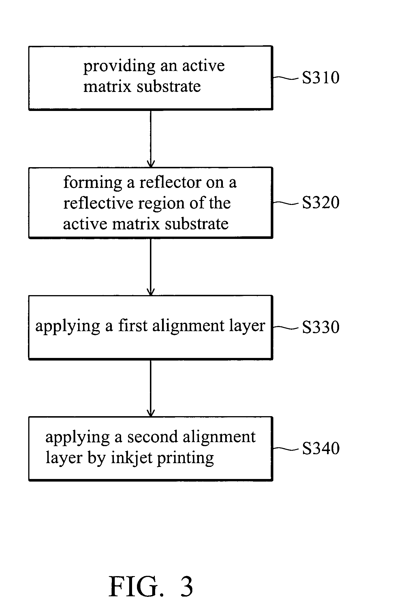
[0023]The invention is directed to a single gap transflective LCD device in which balanced brightness and contrast ratio are exhibited in both the transmissive and reflective regions. Since a substantial recess is created on the transmissive region due to the reflector disposed on the reflective region, a first and a second alignment layers are respectively applied on the transmissive and the reflective regions, or alternatively two different alignment materials are simultaneously inkjet printed on the transmissive and the reflective regions. The invention provides a single gap transflective LC cell including T and R regions with similar retardation changes that provid...


PUM


Abstract

Transflective liquid crystal display devices and fabrication methods thereof. A single cell gap transflective liquid crystal display device includes a first substrate with a reflective region and a transmissive region. A second substrate opposes the first substrate. A liquid crystal layer is disposed between the first and second substrates. A reflective structure is disposed on the first substrate, thereby forming a recess at the transmissive region. A first alignment layer is conformably formed on the first substrate covering the reflective structure, thereby forming a second recess at the reflective region. The second recess is filled with a second alignment, wherein the first and second alignment layers provide different orientations and pre-tilt angles for the liquid crystal layer.

Description

BACKGROUND OF THE INVENTION[0001]1. Field of the Invention[0002]The invention relates to liquid crystal display (LCD) devices, and in particular to reflective LCD devices and fabrication methods thereof[0003]2. Description of the Related Art[0004]Liquid crystal display (LCD) devices have many advantages such as small volume, light weight and low power consumption, and are applicable in a variety of electronic and communication devices including notebook computers, personal digital assistants (PDA), mobile phones and the like due to lighter weight, thinner profile, and increased portability.[0005]A conventional LCD device includes a pair of substrates with opposing electrodes thereon. A liquid crystal layer is interposed between the pair of substrates. An electric field is applied on the opposing electrodes to control liquid crystal molecular orientations in the liquid crystal layer, thereby displaying desirable images. Two alignment layers are separately interposed between the inter...

Claims


Application Information

Patent Timeline
IPC IPC(8): G02F1/1337G02F1/1335
CPCG02F1/133555G02F2202/40G02F2001/133761G02F1/133753G02F1/133761
Inventor HSIAO, CHIH-CHUNCHANG, KU-HSIENCHEN, RU-DEHSIEH, CHENG-HSI
Owner IND TECH RES INST
Learn More