Synthetic anti-ferromagnetic structure with non-magnetic spacer for MRAM applications

a non-magnetic spacer and anti-ferromagnetic technology, applied in the field of mram structure, can solve the problems of “half-selected” cells being more susceptible to unintentional switching of magnetic states, and manufacturability problems

Inactive Publication Date: 2007-08-09
HEADWAY TECH INC
View PDF7 Cites 60 Cited by
  • Summary
  • Abstract
  • Description
  • Claims
  • Application Information

AI Technical Summary

Benefits of technology

[0014] One objective of the present invention is to provide a toggling MRAM structure in which a nearly balanced SAF free layer can be achieved through a strong anti-parallel coupling of two major sub-layers wherein each of the two major sub-layers has at least two minor sub-layers that are ferromagnetically coupled.

Problems solved by technology

This condition makes these “half-selected” cells more susceptible to having their magnetic states unintentionally switched when the selected cell is written.
However, weak anti-ferromagnetic coupling as applied here in either local regions or the full film is very difficult to control during MTJ film depositions and thereby causes a manufacturability issue.

Method used


Image

  • Synthetic anti-ferromagnetic structure with non-magnetic spacer for MRAM applications
  • Synthetic anti-ferromagnetic structure with non-magnetic spacer for MRAM applications
  • Synthetic anti-ferromagnetic structure with non-magnetic spacer for MRAM applications

Examples


Embodiment Construction

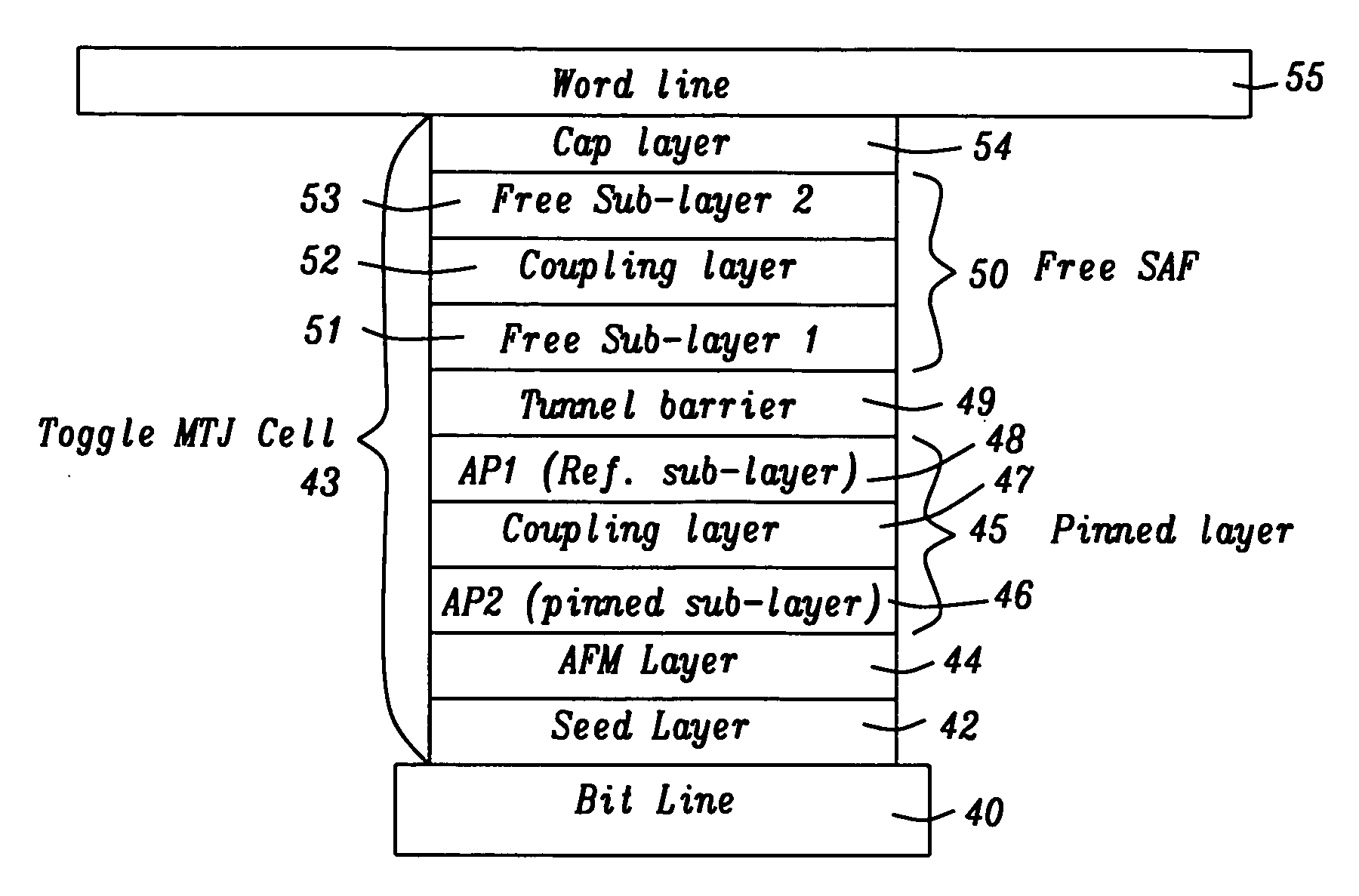
[0032] The present invention is an MRAM structure with a toggle MTJ cell design wherein a SAF free layer has a nearly balanced anti-ferromagnetic (SAF) structure comprised of a first major sub-layer and a second major sub-layer with an anti-ferromagnetic layer therebetween. Within a major sub-layer, there is a plurality of minor magnetic sub-layers with a non-magnetic, parallel coupling layer between adjacent minor sub-layers. The drawings are provided by way of example and are not intended to limit the scope of the invention. Although certain drawings depict a bit line formed below a MTJ and a word line above the MTJ, the designation for bit line and word line may be reversed. Moreover, the terms bit line and word line may be interchanged with other terms such as column line, row line, data line, and digit line and that the MTJ may be a top MTJ, a bottom MTJ, or a dual MTJ as appreciated by those skilled in the art “Write word line” and “write bit line” are terms that identify the ...


PUM


Abstract

A toggle MTJ cell is disclosed that has a nearly balanced SAF free layer with two major sub-layers separated by an anti-parallel coupling layer. Within each major sub-layer, there is a plurality of minor sub-layers wherein adjacent minor sub-layers are separated by a parallel coupling layer. The parallel coupling layer is a non-magnetic layer that may be a one or more of Ta, Cu, Cr, Ru, Os, Re, Rh, Nb, Mo, W, Ir, and V, a metal oxide, or dusting of NiCr, Ta, Cu, or NiFeCr. Magnetic moments of major sub-layers are made to be nearly equal so that the net moment of the SAF free layer is essentially zero. The MTJ cell and SAF free layer preferably have an aspect ratio of from 1 to 5. Ferromagnetic coupling between minor sub-layers enables a lower write current and lower power consumption than conventional toggle cell designs.

Description

RELATED PATENT APPLICATIONS [0001] This application is related to the following: Docket # HT03-009, Ser. No. 10 / 796,387, filing date Mar. 9, 2004; and Docket # HMG05-050, Ser. No. ______, filing date Jan 17, 2006.FIELD OF THE INVENTION [0002] The invention relates to an MRAM structure having a magnetic region comprised of a synthetic anti-ferromagnetic (SAF) free layer with a multilayer structure in which two major sub-layers are strongly anti-parallel coupled through an anti-ferromagnetic coupling layer and minor sub-layers within each of the two major sub-layers are ferromagnetically coupled to lower the write current. BACKGROUND OF THE INVENTION[0003] Magnetic random access memory (MRAM) that incorporates a magnetic tunneling junction (MTJ) as a memory storage cell is a strong candidate to provide a high density, fast (1-30 ns read / write speed), and non-volatile storage solution for future memory applications. An MRAM array is generally comprised of an array of parallel first con...

Claims


Application Information

Patent Timeline
Patent Type & Authority Applications(United States)
IPC IPC(8): G11C11/00
CPCB82Y25/00B82Y40/00G11C11/16H01L43/08H01F10/3272H01F41/302H01F10/3254H10N50/10
Inventor GUO, YIMIN
Owner HEADWAY TECH INC
Why Eureka
Try Eureka