Image compression method, image compression device, image transmission system, data compression pre-processing apparatus, and computer program

Active Publication Date: 2007-08-09
TOA CORP
View PDF12 Cites 24 Cited by
  • Summary
  • Abstract
  • Description
  • Claims
  • Application Information

AI Technical Summary

Benefits of technology

[0025] The present invention can provide an image compression method and an image compression apparatus that can compress an image while making an image quality different among small regions within the image, and that can perform an expansion processing without using a dedicated image expansion apparatus. The present invention can also provide a data compression prepro

Problems solved by technology

It is, therefore, disadvantageously necessary to employ not only the dedicated image compression apparatus but also a dedicated image expansion apparatus.
Due to this, a general-purpose JPEG compressor such as a JPEG chipset can not be employed as the data compression apparatus and the data compression apparatus is disadvantageously made expensive.
Due to this, even after the image data

Method used


Image

  • Image compression method, image compression device, image transmission system, data compression pre-processing apparatus, and computer program
  • Image compression method, image compression device, image transmission system, data compression pre-processing apparatus, and computer program
  • Image compression method, image compression device, image transmission system, data compression pre-processing apparatus, and computer program

Examples


first embodiment

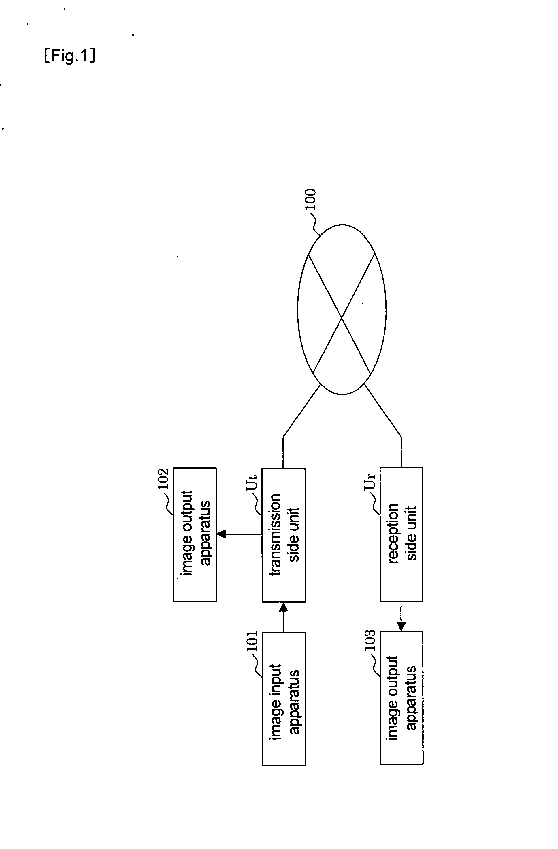
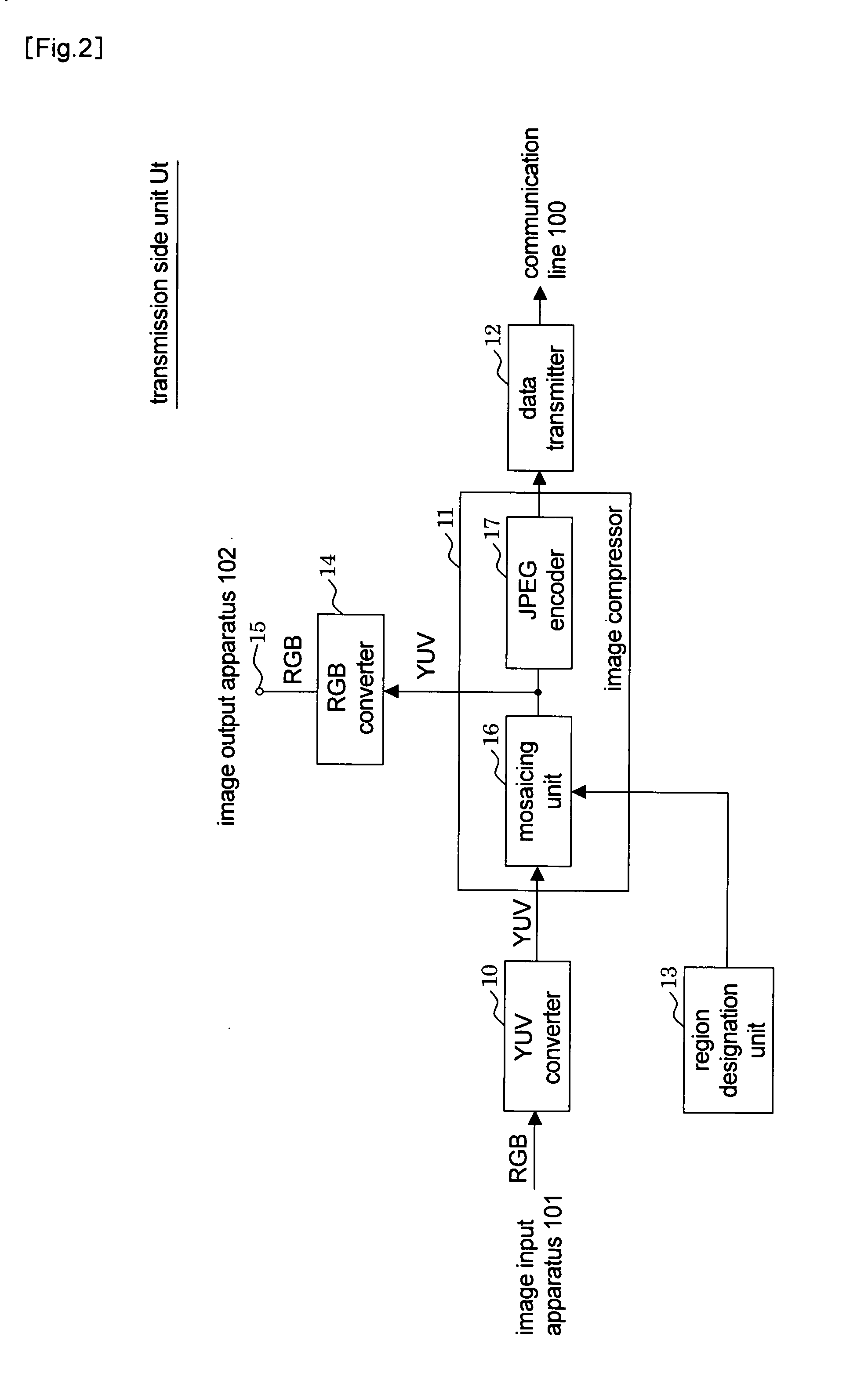
[0026]FIG. 1 is a block diagram of one example of a configuration of an image compression and expansion system according to a first embodiment of the present invention and depicts an example of an image transmission system. This image transmission system includes a transmission side unit Ut and a reception side unit Ur connected to each other by a communication line 100. The image transmission system can compress image data and transmit the compressed image data from the transmission side unit Ut to the reception side unit Ur. In the present embodiment, image data of an image input apparatus 101 connected to the transmission side unit Ut is transmitted to an image output apparatus 103 connected to the reception side unit Ur. In addition, an image output apparatus 102 connected to the transmission side unit Ut can monitor the image data to be transmitted.

[0027] The communication line 100, which is constituted by a wired or wireless communication line for transmitting digital data, i...

second embodiment

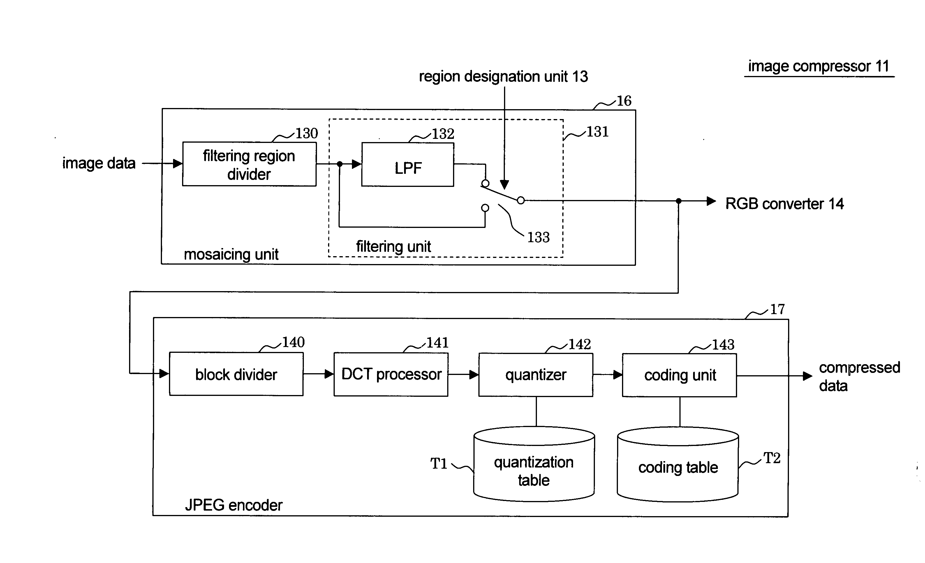
[0062] In the first embodiment, the instance of making a filtering region coincide with the JPEG block has been described. In the present embodiment, by contrast, an instance in which the filtering region differs in size and shape from the JPEG block will be described.

[0063] FIGS. 13(a) to 13(e) depict an example of a relationship between the filtering region and the JPEG block that will be described below. In FIG. 13, a reference symbol FA denotes the filtering region and a reference symbol BL denotes the JPEG block.

[0064] An instance in which the filtering region is larger than the JPEG block will first be described. A filtering region is assumed as a cluster consisting of two or more adjacent JPEG blocks, and the filtering region is subjected to the unifying. In this case, the DC coefficient for each of the JPEG blocks obtained by the DCT processing performed within the JPEG encoder 17 is equal. Due to this, if these JPEG blocks are adjacent to one another in a processing direc...

third embodiment

[0073]FIG. 14 is a block diagram of an example of an image transmission system according to a third embodiment of the present invention. This image transmission system includes a mosaicing unit Um, a monitoring unit Ud, a data compressing unit Uc connected to one another through a first communication line 110, and a reception side unit Ur connected to the data compressing unit Uc through a second communication line 111.

[0074] An image input apparatus 101 is connected to the mosaicing unit Um, mosaics image data from the image input apparatus 101 and transmits the mosaiced image data to the first communication line 110 without performing the data compression processing on the mosaiced image data. An image output apparatus 102 is connected to the monitoring unit Ud. If the monitoring unit Ud receives the mosaiced image data from the mosaicing unit Um, the monitoring unit Ud converts the image data into the image data in the RGB format and causes the resultant image to be displayed on...


PUM


Abstract

[PROBLEMS] To provide an image compression method capable of performing compression with different image qualities within an image. [MEANS FOR SOLVING PROBLEMS] In a mosiac processing unit (16), area division means (130) divides input image data into a plurality of filtering areas and at least some of the filtering areas are subjected to unification processing for each of the filtering areas by a filtering unit (131). On the other hand, a JPEG encoder (17) divides the image data after the mosiac processing into a plenty of rectangular block areas and each of the block areas is subjected to the DCT processing and quantization processing. Here, the filtering area consists of adjacent one or more than one sets of rectangular areas consisting of two or more pixels obtained by equally dividing the aforementioned block area by 2n (n is a natural number).

Description

TECHNICAL FIELD OF THE INVENTION [0001] The present invention relates to an image compression method, an image compression apparatus, an image transmission system, a data compression preprocessing apparatus, and a computer program. More specifically, the present invention relates to an improvement of a data compression method such as a JPEG compression method for performing an orthogonal transform and a quantization on image data for every block region obtained by dividing the image data into a plurality of block regions. BACKGROUND ART [0002] As methods for compressing and expanding image data constituted by a still image, there are widely known JPEG (Joint Photographic Expert Group) standards standardized according to CCITT (International Telegraph and Telephone Consultative Committee) and ISO (International Standards Organization). In the JPEG standards, an image data compression method performed by dividing a frame image into a plurality of blocks in such a way that 8×8 pixels c...

Claims


Application Information

Patent Timeline
IPC IPC(8): G06K9/36H04N1/00H04N1/41H04N19/117H04N19/167H04N19/60H04N19/625H04N19/80H04N19/91
CPCH04N19/176H04N19/60H04N19/117H04N19/14H04N19/85H04N19/154H04N19/162H04N19/17H04N19/80H04N19/137
Inventor MOROHASHI, TOSHIO
Owner TOA CORP
Why Eureka
Try Eureka