Compression bandage with H-anchor tightening means

Inactive Publication Date: 2007-08-09
HARDER ROBERT H
View PDF12 Cites 26 Cited by
  • Summary
  • Abstract
  • Description
  • Claims
  • Application Information

AI Technical Summary

Benefits of technology

[0008] This invention allows an individual to place a bandage on a wound and, with one hand if nec

Problems solved by technology

Some past tightening devices that are attached to trauma bandages do not allow a sufficiently large force to be placed on the tightening device to stop arte

Method used


Image

  • Compression bandage with H-anchor tightening means
  • Compression bandage with H-anchor tightening means
  • Compression bandage with H-anchor tightening means

Examples


Embodiment Construction

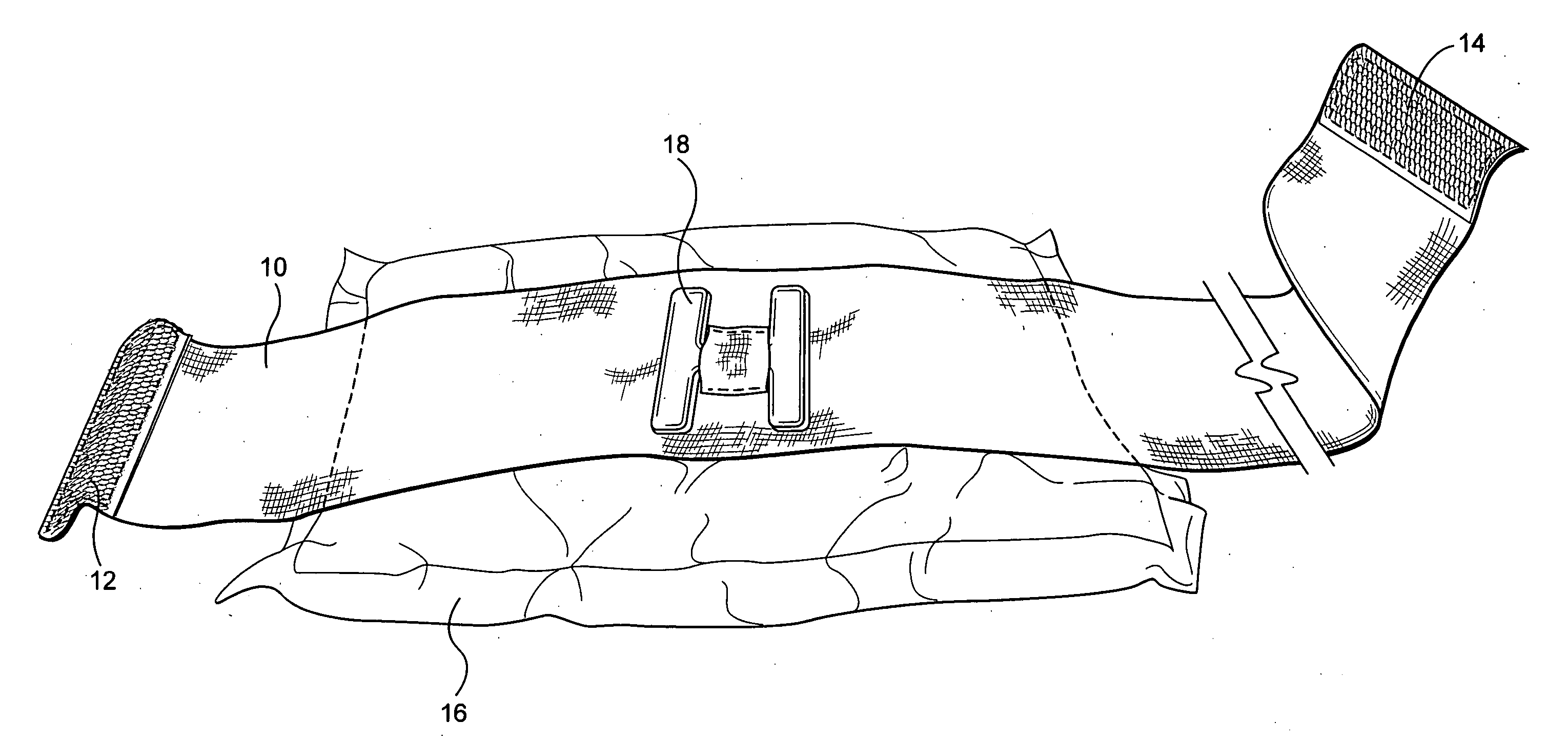
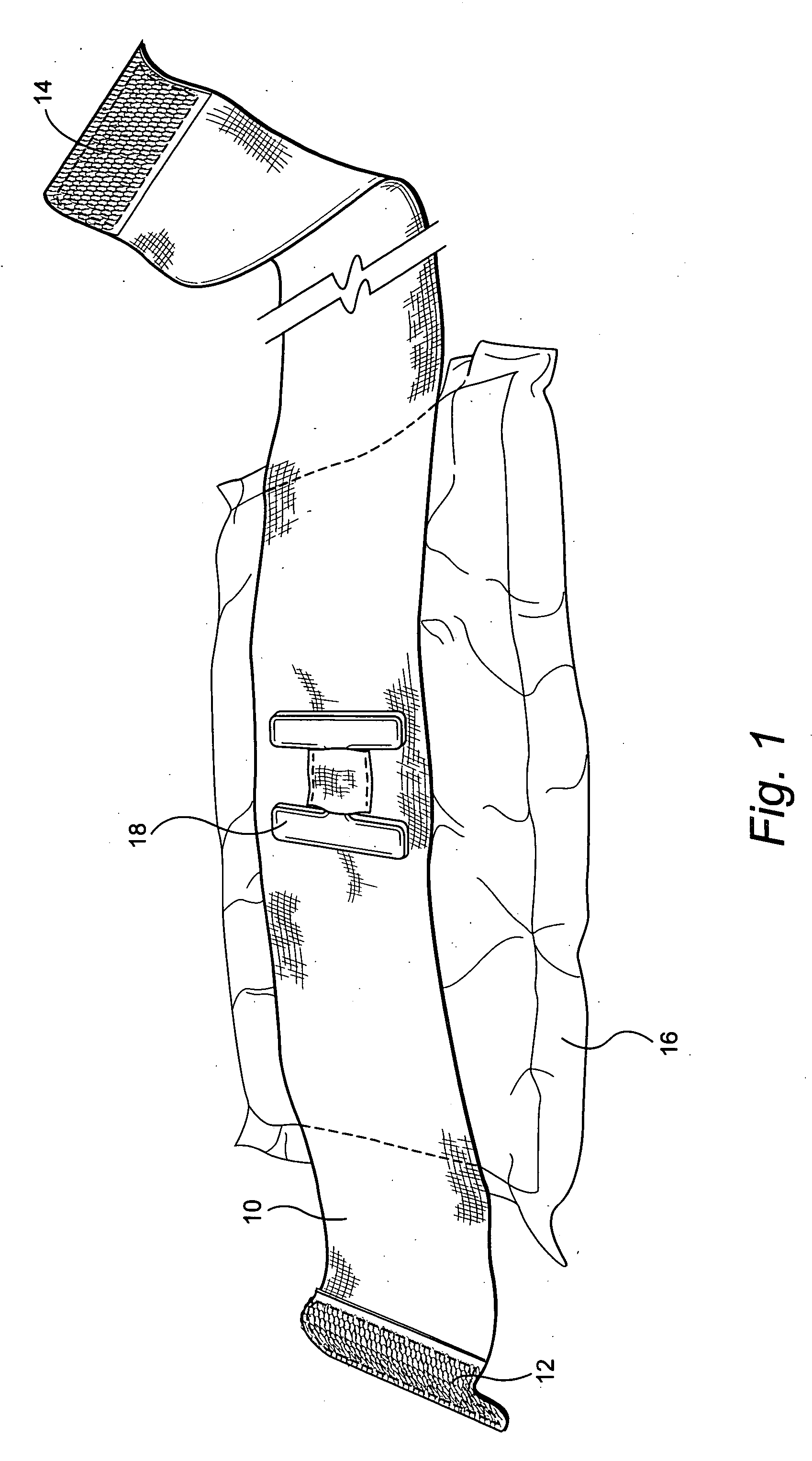
[0015] The present invention, an elastic bandage, comprises a strip of material 10 in the form of a roll, preferably at least 3″ to 6″ in width, and 48″ to 60″ long. At each end of the material male Velcro® strips 12, 14 are fastened. Near one end of the elastic roll (the ends of the material are defined as the near end and the far end), a high absorbent pad 16, in a preferred embodiment at least 5″×8,″ is attached. In one embodiment, shown in FIG. 1, at the center of the pad, but on the opposite side of the material from the absorbent pad 16, an anchoring point, in a preferred embodiment, an H-anchor 18 is attached. The H-anchor has two vertical legs located transversely across the bandage and the legs are connected by a cross-piece (forming the letter “H”) which may be fastened to the bandage in any manner, i.e., by gluing, by sewing a transverse tab (as shown), etc.

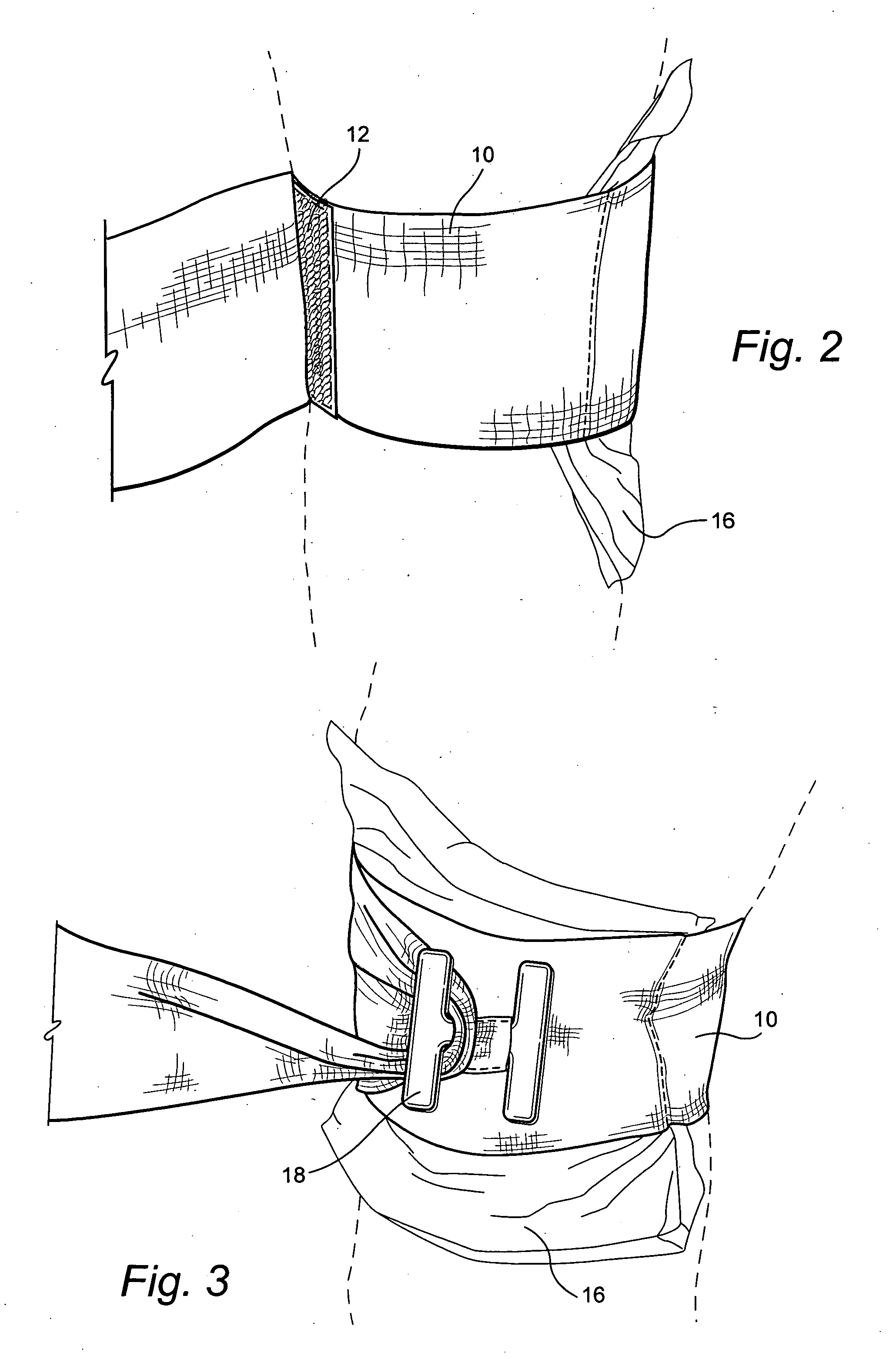
[0016] After the pad 16 is located over the wound, the elastic roll is wrapped once around the extremity. The use o...


PUM


Abstract

Disclosed is a strip of bandaging material having Velcro® strips at either end on opposite sides of the material. An absorbent pad is fixed near one end and on the side opposite the Velcro® strip. On the side opposite the absorbent pad, an S hook is provided with one end fastened to the material and the other end free. The absorbent pad is located over the wound and the longer end of material is wound around the extremity and fixed in place with the Velcro® strip at the near end of the material. The remaining material is passed through the hook and pulled back in order to apply pressure to the wound and reduce blood loss. The remainder of the material is wrapped around the extremity and secured in place with a Velcro® strip and/or a barrette clip on the far end.

Description

BACKGROUND OF THE INVENTION [0001] 1. Field of the Invention [0002] The current compression bandages that are employed to give first aid to trauma wounds are sometimes difficult to adequately tighten securely over the wound. For wounds that are aggressively bleeding, an increase in compression over the wound site is necessary. [0003] 2. Discussion of Prior Art [0004] Some past tightening devices that are attached to trauma bandages do not allow a sufficiently large force to be placed on the tightening device to stop arterial bleeding. In addition, some past bandages needed hand tied knots to fasten the bandage to the wound, resulting in loosening of the bandage on the trauma. [0005] A solution to the need for the problem of hand tied knots was the subject matter of U.S. Pat. No. 6,593,508 issued to the current inventor, Robert H. Harder on Jul. 15, 2003 with a divisional of that patent issued Jul. 13, 2004 as U.S. Pat. No. 6,762,338 (hereinafter “the Harder patents”). The Harder pat...

Claims


Application Information

Patent Timeline
IPC IPC(8): A61L15/00
CPCA61B17/1322A61F13/00A61F13/00038A61F2013/00468A61F17/00A61F2013/00106A61F15/00
Inventor HARDER, ROBERT H.
Owner HARDER ROBERT H
Why Eureka
Try Eureka