Method of compression molding thermoplastic material

a thermoplastic material and compression molding technology, applied in the field of compression molding thermoplastic materials, can solve the problems of inability the need to precisely define the position of the half-mold, and the inability to precisely move the platen during compression, so as to achieve less shearing stress, improve mechanical properties, and reduce cycle time

Inactive Publication Date: 2007-08-16
SUMITOMO SHI DEMAG PLASTICS MACHINERY
View PDF1 Cites 2 Cited by
  • Summary
  • Abstract
  • Description
  • Claims
  • Application Information

AI Technical Summary

Benefits of technology

[0028] According to another feature of the present invention, injection of melt may be continued as the mold closes, i.e. after reaching the mold opening position defined by the compression gap. This further reduces the cycle time. Optionally, compression may last beyond the injection stage and application of the holding pressure. It is, however, also possible to continue the injection and holding pressure application phases after completion of the compression phase. The process profile is also dependent on the material being processed.
[0029] According to another feature of the present invention, mold opening, in particular when realized by the injected melt, may be assisted by moving cores which are provided in the area of the mold. The cores may be spring-loaded and thereby assist the passive opening of the mold in particular during the initial phase. Of course, the cores may also be actively controlled. Currently preferred is however the provision of spring-loaded cores which must be positioned when the mold closes. As an alternative, it is also possible to use, for example, pre-stressed or also controllable vertical flash faces to assist the opening process, at least during the initial phase.
[0030] Compression molding is oftentimes used to produce large-area parts, as demanded in the automobile industry for example. These parts are often produced in the presence of cores to clear respective recesses in the flat parts from melt. Assisting the passive mold opening by pre-loaded cores may be beneficial because injected melt is subjected at least initially to a reduced pressure and exposed to less shearing stress.
[0031] In particular, when using cores, it may be advantageous to keep the mold closed after the closing step and before the start of the injection step to prevent a premature opening of the mold in the absence of melt introduction.
[0032] According to another feature of the present invention, the movable platen may be subjected to a defined counterpressure during passive mold opening, realized by pressure buildup as a result of injected m...

Problems solved by technology

However, for a number of reasons, the various proposals are endowed with drawbacks and shortcomings relating for example to manufacturing techniques or to the effect that is hoped to be obtained but may not always be realized.
For example, one drawback common to all prior art proposals is the requirement to precisely define the position of the half-molds bef...

Method used


Image

  • Method of compression molding thermoplastic material
  • Method of compression molding thermoplastic material
  • Method of compression molding thermoplastic material

Examples


Embodiment Construction

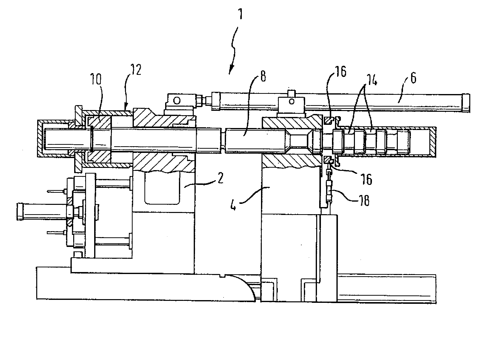
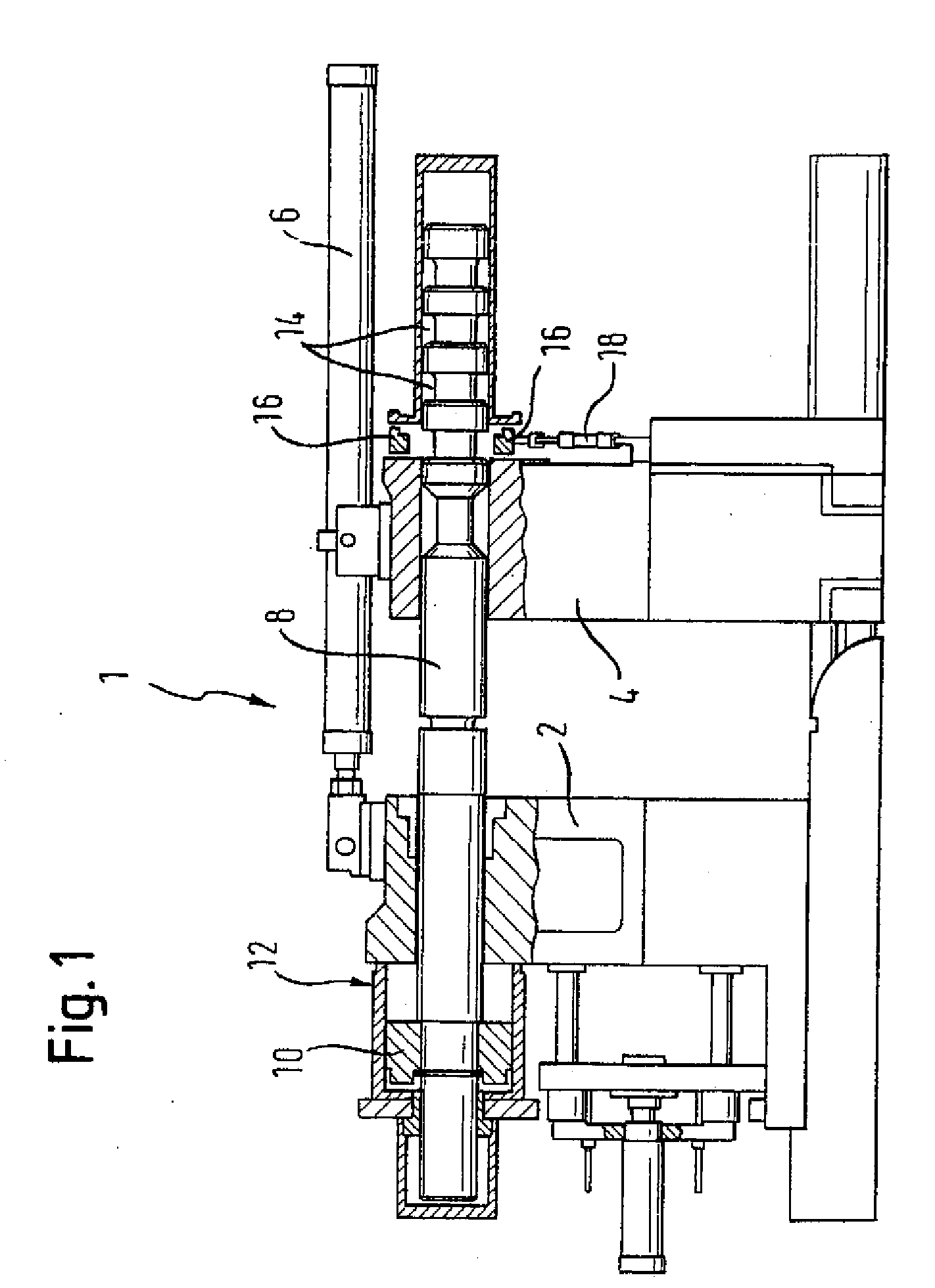
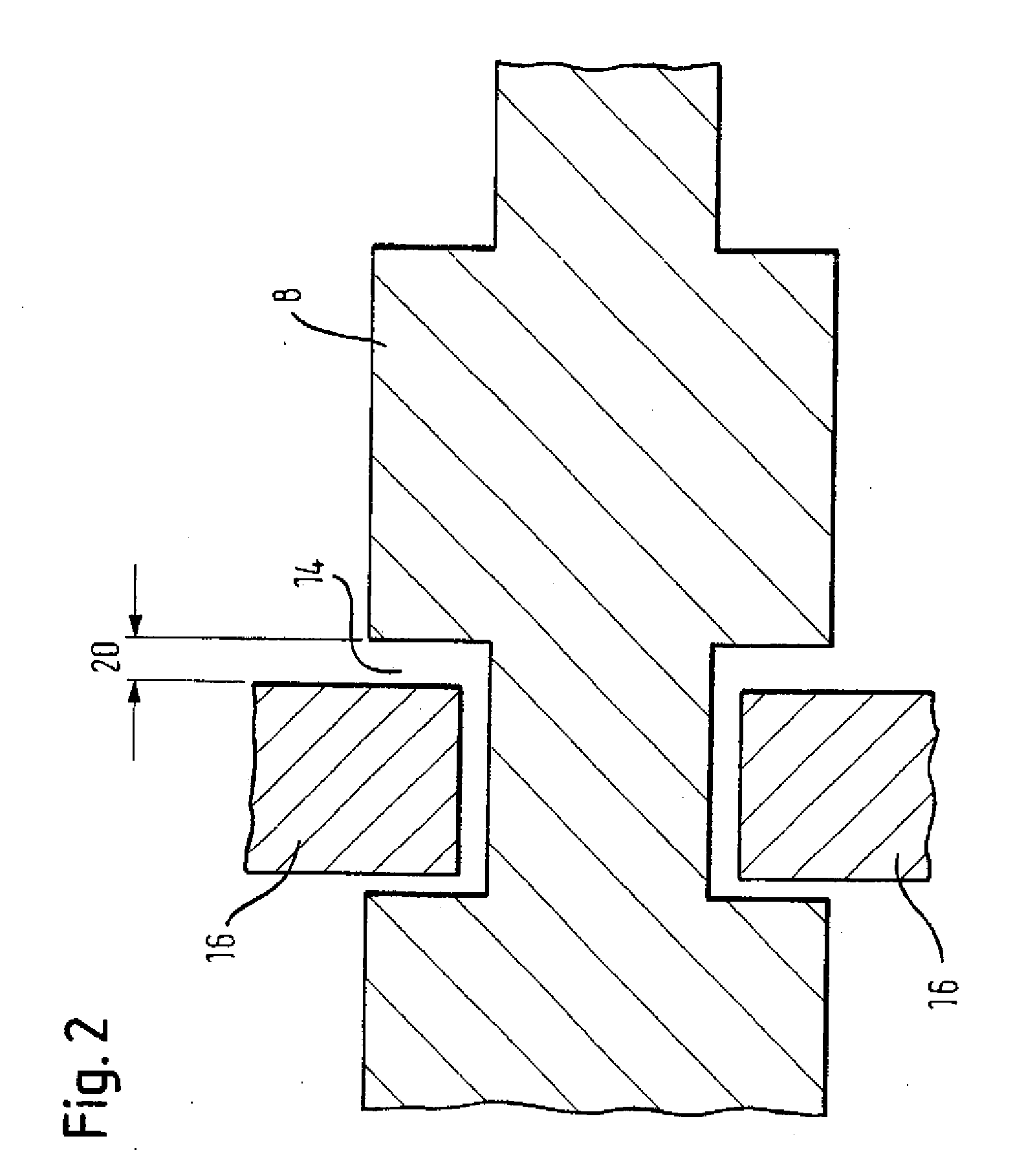
[0038] Throughout all the Figures, same or corresponding elements are generally indicated by same reference numerals. These depicted embodiments are to be understood as illustrative of the invention and not as limiting in any way. It should also be understood that the figures are not necessarily to scale and that the embodiments are sometimes illustrated by graphic symbols, phantom lines, diagrammatic representations and fragmentary views. In certain instances, details which are not necessary for an understanding of the present invention or which render other details difficult to perceive may have been omitted.

[0039] Turning now to the drawing, and in particular to FIG. 1, there is shown a schematic longitudinal section of a clamping unit, generally designated by reference numeral 1 and forming part of a two-platen injection molding machine. The clamping unit 1 includes a movable platen 2 and a fixed platen 4, whereby the movable platen 2 can be moved by a displacement cylinder 6 i...


PUM

PropertyMeasurementUnit
Forceaaaaaaaaaa
Pressureaaaaaaaaaa
Sizeaaaaaaaaaa

Abstract

In a method of compression molding thermoplastic material, a compression gap is set between half-molds of a mold having fixed and movable platens for respective attachment of the half-molds. After setting the compression gap, the mold is closed and the platens are locked by moving locking elements into respective receiving elements. Injection of plasticized material then commences into a cavity formed between the half-molds when the mold is closed. The mold then opens as a result of pressure generated by the injected plasticized material until a distance between the half-molds corresponds to the compression gap. Subsequently, the mold undergoes a closing movement through application of a clamping force, thereby compressing the plasticized material.

Description

CROSS-REFERENCES TO RELATED APPLICATIONS [0001] This application is a continuation of prior filed copending PCT International application no. PCT / EP2005 / 054358, filed Sep. 5, 2005, which designated the United States and has been published but not in English as International Publication No. WO 2006 / 042772 A1 and on which priority is claimed under 35 U.S.C. §120, and which claims the priority of German Patent Application, Serial No. 10 2004 051 324.4, filed Oct. 20, 2004, pursuant to 35 U.S.C. 119(a)-(d), the contents of which are incorporated herein by reference in its entirety as if fully set forth herein.BACKGROUND OF THE INVENTION [0002] The present invention relates to a method of compression molding thermoplastic material. [0003] Nothing in the following discussion of the state of the art is to be construed as an admission of prior art. [0004] There are various proposals of compression molding thermoplastics. For example, published European Pat. Appi. No. 0 244 783 describes a m...

Claims


Application Information

Patent Timeline
IPC IPC(8): B29C45/00
CPCB29C45/561B29C2045/563B29C45/6728
Inventor BESOLD, UDO
Owner SUMITOMO SHI DEMAG PLASTICS MACHINERY
Why Eureka
Try Eureka