Spark plug for internal combustion engine

a technology for spark plugs and internal combustion engines, which is applied in spark plugs, basic electric elements, electric devices, etc., can solve the problems of fuel being liable to flow out of the specified area into the side area, and the fuel being difficult to clamp onto the facing surface in the specified area, so as to and reduce the occurrence of fuel bridging

Inactive Publication Date: 2007-08-16
DENSO CORP
View PDF7 Cites 25 Cited by
  • Summary
  • Abstract
  • Description
  • Claims
  • Application Information

AI Technical Summary

Benefits of technology

[0013]The present invention has been completed with the above view in mind and has an object to provide a spark plug for an internal combustion engine which spark plug has an excellent fuel clamping resistance and fuel bridging resistance.
[0015]With the spark plug set forth above, the facing surface of the ground electrode is set to have a width equal to or less than 1.6 mm. Therefore, even if fuel is caused to adhere onto the facing surface of the ground electrode in a specified area around the spark discharge gap, fuel is liable to flow out of the specified area into side areas. In addition, even if fuel is adhered onto the ground electrode and flows to the facing surface thereof, this fuel flows into the side areas of the facing surface. Thus, fuel becomes hard to clamp onto the facing surface in the specified area. This results in capability of suppressing the occurrence of fuel clamping, while making it possible to minimize the occurrence of fuel bridging. Thus, the spark plug can have increased ignitability and startability.
[0016]As set forth above, the present invention makes it possible to provide a spark plug for an internal combustion engine with increased fuel clamping resistance and fuel bridging resistance.

Problems solved by technology

Therefore, even if fuel is caused to adhere onto the facing surface of the ground electrode in a specified area around the spark discharge gap, fuel is liable to flow out of the specified area into side areas.
Thus, fuel becomes hard to clamp onto the facing surface in the specified area.

Method used


Image

  • Spark plug for internal combustion engine
  • Spark plug for internal combustion engine
  • Spark plug for internal combustion engine

Examples


first embodiment

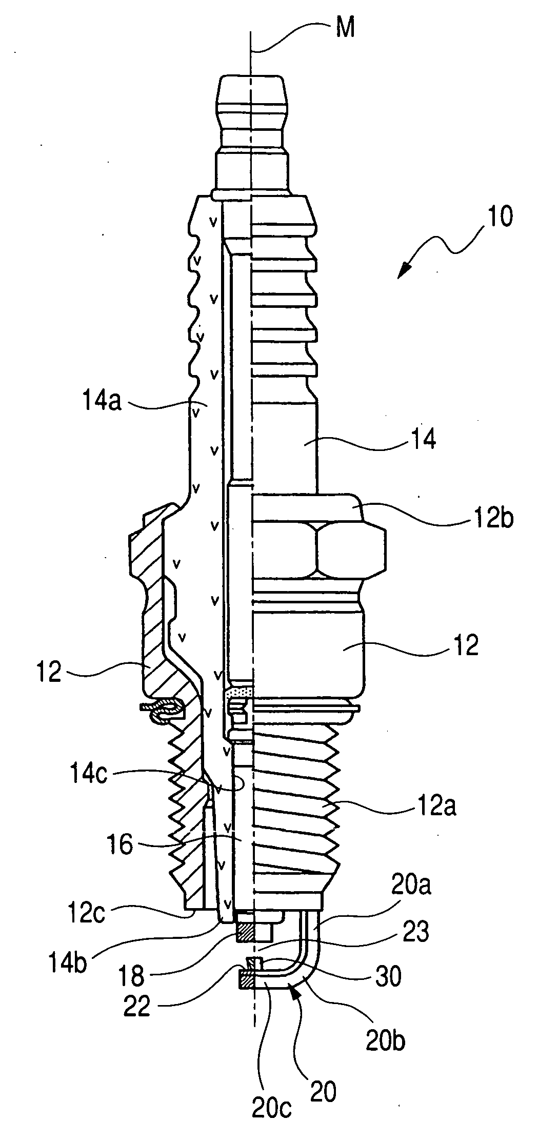
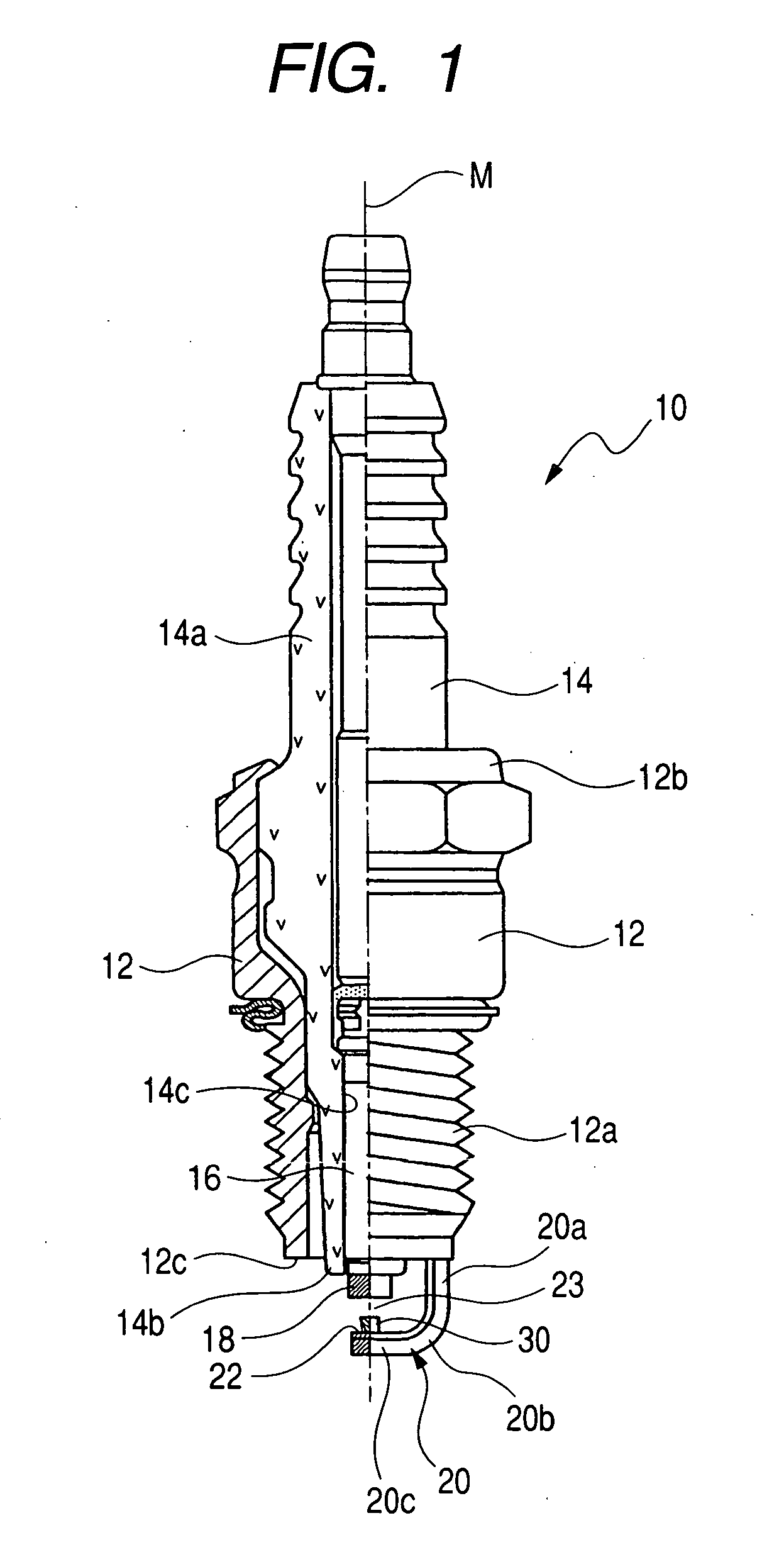
[0036]A spark plug of a first embodiment according to the present invention is described below in detail with reference to FIG. 1 to 3 of the accompanying drawings.

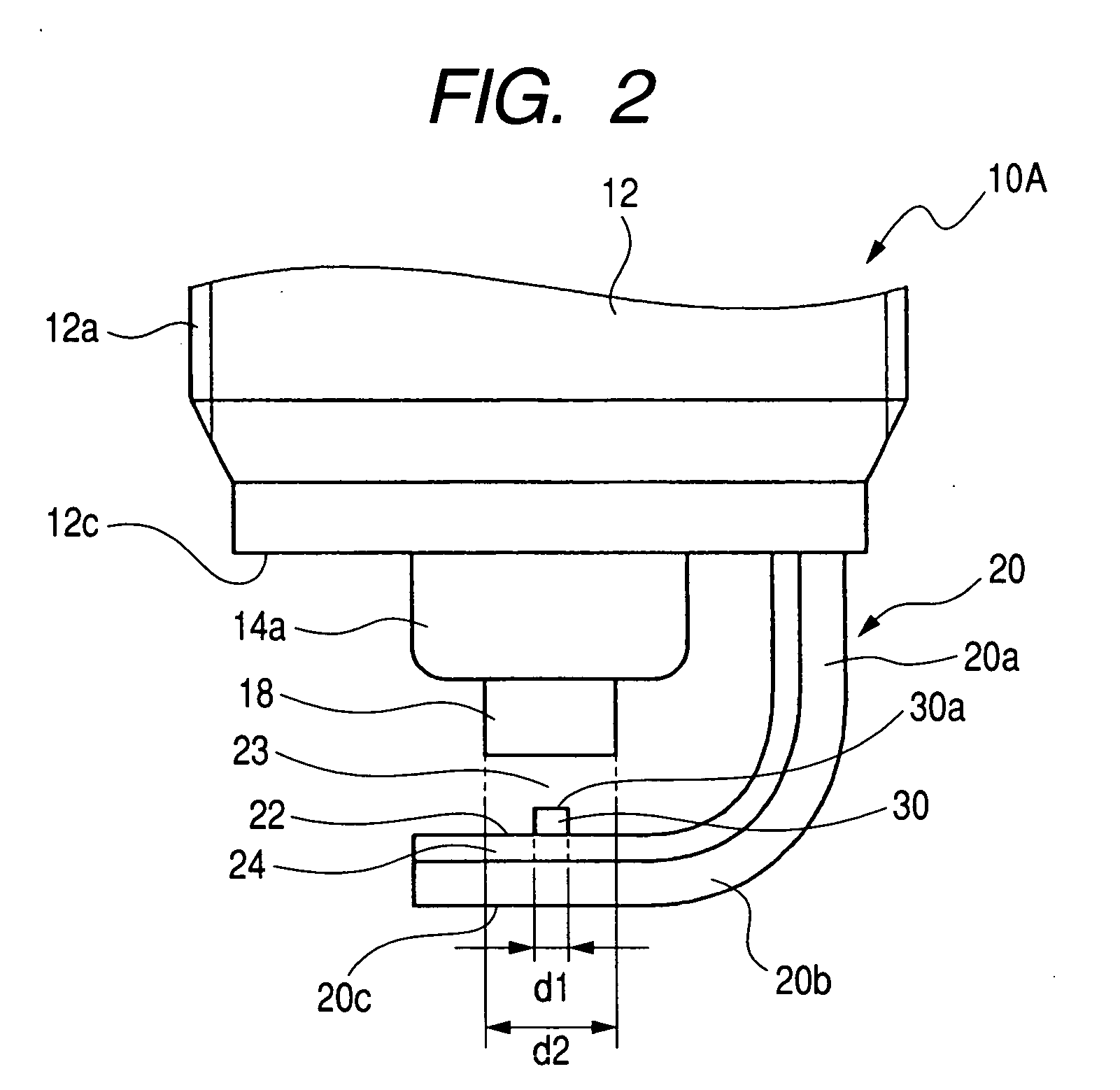
[0037]FIG. 1 is a semi-cross sectional view illustrating an overall structure of the spark plug 10 of the first embodiment according to the present invention; FIG. 2 is an enlarged side view illustrating an area around an igniting section of the spark plug 10; and FIG. 3 is an enlarged front view illustrating an area around the igniting section of the spark plug 10

[0038]The spark plug 10 may be used as an igniting means of an internal combustion engine to be used in, for instance, a motor vehicle, a cogeneration system and a gas pressure feed pump or the like with the engine having an engine head (not shown) formed with a threaded bore to which the spark plug of the present invention is screwed in a fixed place.

[0039]As shown in FIGS. 1 to 3, the spark plug 10 includes a cylindrical metal shell 12, made of electrically co...

second embodiment

[0060]A spark plug of a second embodiment is described below with reference to FIGS. 4 and 5. FIG. 4 is an enlarged front view showing the spark plug of the present embodiment. FIG. 5 is an enlarged side view of the spark plug of the present embodiment.

[0061]As shown in FIGS. 4 and 5, the spark plug 10A comprises a ground electrode 20A that has no noble metal chip.

[0062]With the spark plug 10A of the present embodiment, a spark discharge gap 23 is provided between a distal end of a center electrode 16 and a facing surface 22A of an end portion of the ground electrode 20A. The facing surface 22A is set to have the same width “w”, laying in a value equal to or less than 1.6 mm, as that of the facing surface 22 of the ground electrode 22 of the first embodiment.

[0063]The spark plug 10A is similar in other structure to the spark plug 10 of the first embodiment and, so, description of the same structure is herein omitted for the sake of simplification.

[0064]With the present embodiment, n...

third embodiment

[0067]A spark plug of a third embodiment is described below with reference to FIGS. 6 and 7. FIG. 6 is an enlarged front view showing the spark plug of the present embodiment. FIG. 7 is an enlarged side view of the spark plug of the present embodiment.

[0068]As shown in FIGS. 6 and 7, the spark plug 10B comprises a ground electrode 20B, formed in a rectangular shape in cross section, which has a facing surface 22B on which a noble metal chip 30B is joined so as to protrude in a spark discharge gap 23B in face-to-face relationship with a distal end of a center electrode 16.

[0069]With such a structure of the spark plug 10B of the present embodiment, the facing surface 22B of the ground electrode 20B is set to have a width “u” falling in a value from 2.2 to 2.8 mm.

[0070]The spark plug 10B of the present embodiment has the same other advantages as those of the spark plug 10 of the first embodiment and, therefore, redundant description of these advantages is herein omitted.

[0071]With the ...


PUM


Abstract

A spark plug for an internal combustion engine is disclosed having a metal shell having an outer periphery formed with a mounting thread, a porcelain insulator fixedly secured to the metal shell on a central axis thereof, a center electrode retained within the porcelain insulator along a central axis thereof with a distal end located outside the porcelain insulator, and a ground electrode joined to the metal shell and having an end associated with the distal end of the center electrode to define therebetween a spark discharge gap. The ground electrode includes a facing surface intersecting the central axis of the center electrode and having a width equal to or less than 1.6 mm.

Description

CROSS REFERENCE TO RELATED APPLICATIONS[0001]This application is based on Japanese Patent Application Nos. 2006-35399, filed on Feb. 13, 2006, and 2006-266829, filed on Sep. 29, 2006, the contents of which are hereby incorporated by reference.BACKGROUND OF THE INVENTION[0002]1. Field of the invention[0003]The present invention relates to spark plugs for internal combustion engines and, more particularly, to a spark plug for use in a motor vehicle, a cogeneration system and a gas pressure feed pump or the like.[0004]2. Description of the Related Art[0005]In the related art, attempts have heretofore been made to provide spark plugs for use in internal combustion engines to be used as igniting means of the internal combustion engines of motor vehicles or the like.[0006]The spark plugs usually include center electrodes and ground electrodes between which spark discharge gaps are provided. Applying a high voltage across the center electrode and the ground electrode allows a spark dischar...

Claims


Application Information

Patent Timeline
Patent Type & Authority Applications(United States)
IPC IPC(8): H01T13/20
CPCH01T13/20H01T13/39H01T13/32
Inventor ISHINADA, TEIJIHORI, TSUNENOBU
Owner DENSO CORP
Why Eureka
Try Eureka