Alarm system

a technology of alarm system and alarm system, applied in the field of alarm system, can solve the problems of system not dynamic, inability to automatically update, and large volume, and achieve the effect of reducing the number of alarms

Inactive Publication Date: 2007-08-16
VENDOLOCUS
View PDF21 Cites 44 Cited by
  • Summary
  • Abstract
  • Description
  • Claims
  • Application Information

AI Technical Summary

Benefits of technology

[0031] In this connection, an additional advantage is obtained if the sensor system comprises at least one of the following sensors: accelerometer/silicon crystal, microphone, frequency transmitters, strain gauges, camera, temperature sensors, UV/photocells, electronic noses, anemometers, infrared sensors, gamma transducers, laser sensors, inductive sensors, flow sensors, level transducers, tension gauges and pressure gauges.
[0032] In this connection, an additional advantage is obtained if each positioning member consists of at least one of the following units: GPS unit, GPRS unit and GSM

Problems solved by technology

A disadvantage of the above-mentioned known system is that it is not a flexible solution.
Another disadvantage is that the system is not dynamic and cannot be updated automatically.
A disadvantage of the above-mentioned known alarm system is that it is relatively bulky since it, among other things, comprises a keyboard panel.
Another disadvantage is that the alarm system is not dynamic and cannot be updated automatically.
They are space-requiring and cannot be placed optionally.
The solutions are expensive.
The solutions are not dynamic or interactive, and cannot be controlled via web or wap.
The solutions comprise buttons and/or displays that make them dearer and constitute sources of error as well as make it more difficult for users.
Th

Method used


Image

  • Alarm system
  • Alarm system
  • Alarm system

Examples


Embodiment Construction

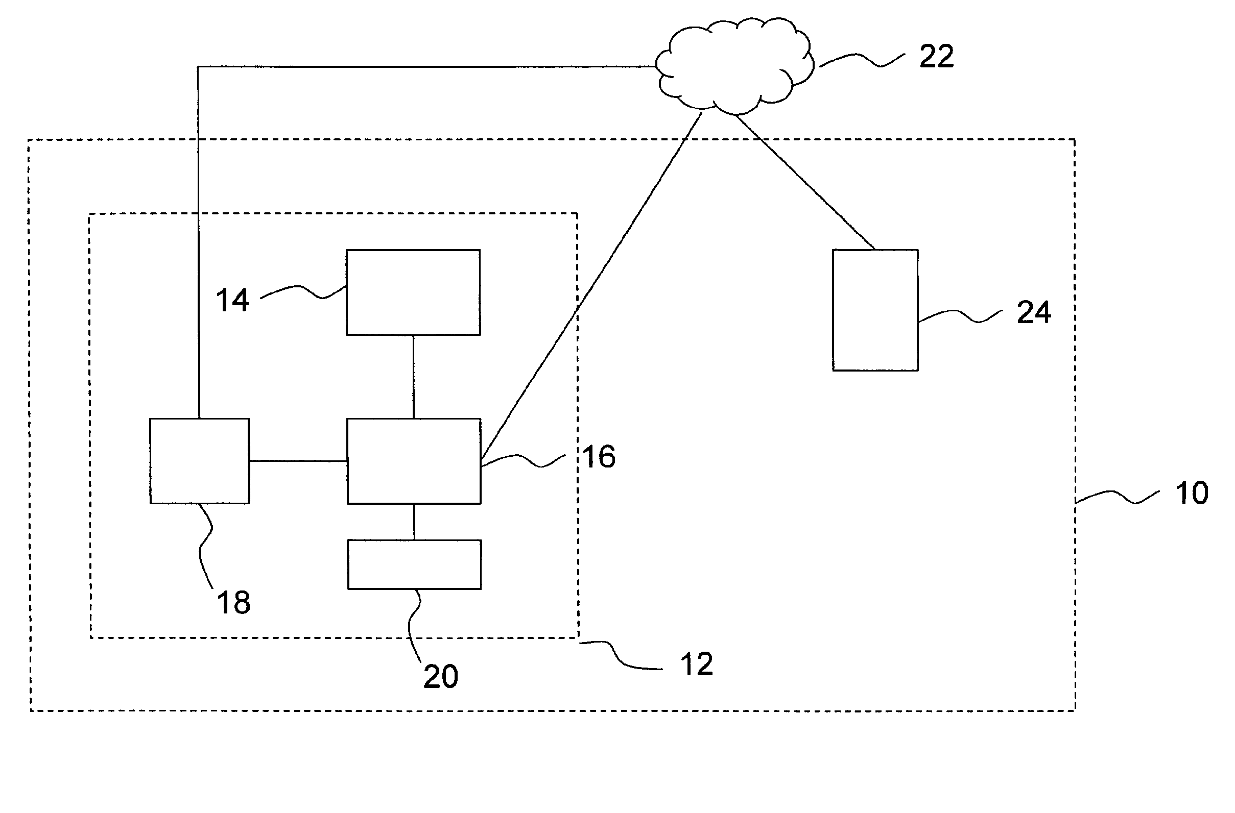
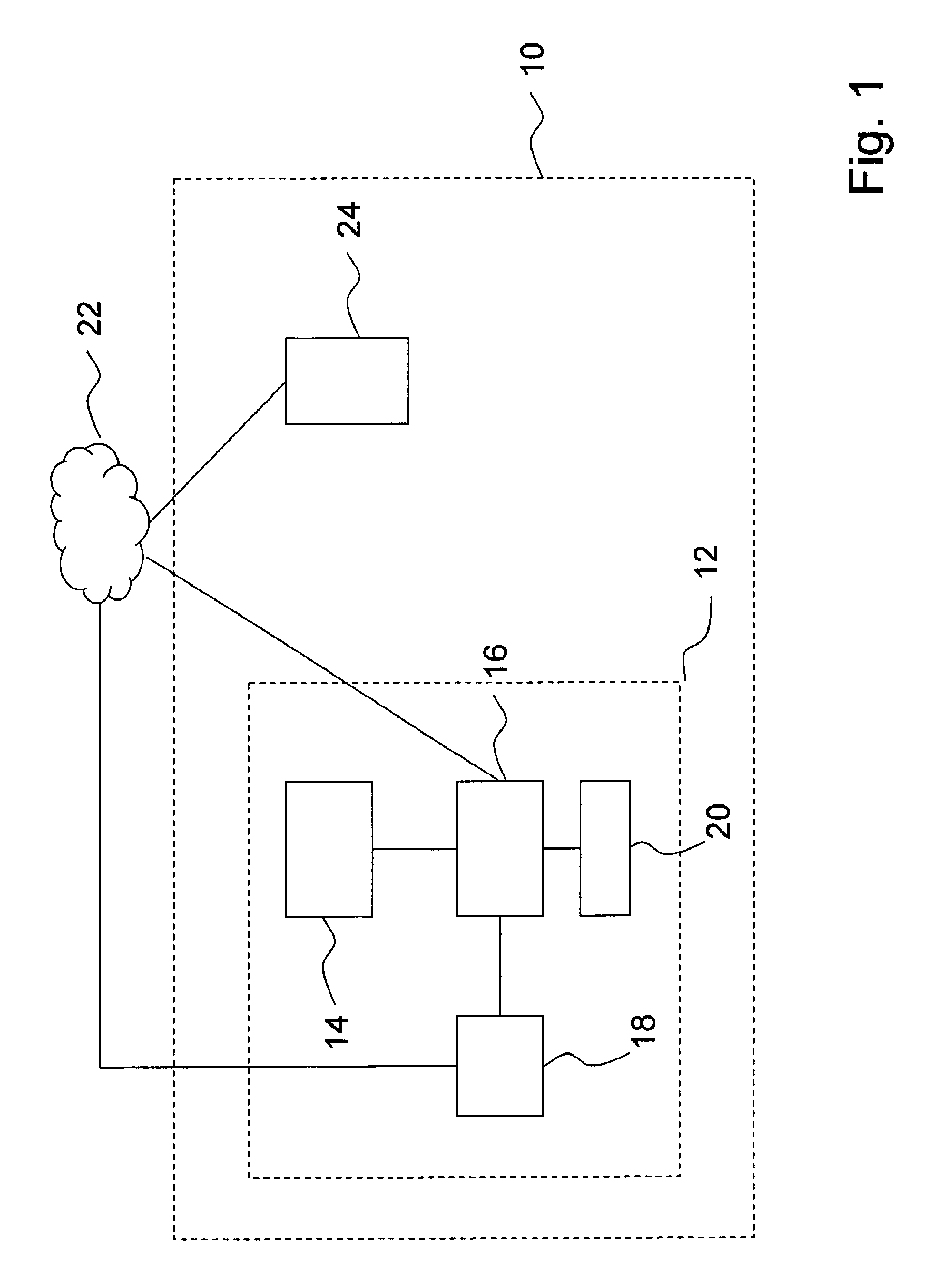
[0058] In FIG. 1, a block diagram is shown of an alarm system 10 according to the present invention. The alarm system 10 is intended to trigger an alarm signal upon deviation from at least one environment-dependent reference predetermined for a specific environment. The alarm system 10 comprises at least one portable unit 12 intended to be placed in said environment. For the sake of simplicity, only one portable unit 12 is shown in FIG. 1, but it is pointed out for the sake of completeness that the number of portable units 12 may be any number suitable for a specific application. Each portable unit 12 has a size not greater than a mobile telephone. As is seen in FIG. 1, each portable unit 12 comprises a sensor system 14 adapted for detecting different states comprising at least one of vibrations relative position changes or accelerations. Furthermore, each portable unit 12 comprises a processor member 16 connected to the sensor system 14 and adapted for the comparison of signals rec...


PUM


Abstract

The present invention relates to an alarm system intended to trigger an alarm signal upon deviation from at least one environment-dependent reference predetermined for a specific environment. The alarm system comprises at least one portable unit intended to be placed in said environment, which unit has a size corresponding to a mobile telephone. Each unit comprises a sensor system adapted for detecting different states comprising at least vibrations. Furthermore, the alarm system comprises a processor member connected to the sensor system and adapted for the comparison of signals received from the sensor system and said predetermined environment-dependent reference/references. The alarm system further comprises a communication member connected to the processor member and adapted for wireless communication upon, for instance, the triggering of an alarm signal. Furthermore, the alarm system comprises a memory member connected to the processor member via a distributed computer network and adapted for the storage of said predetermined reference/references.

Description

FIELD OF THE INVENTION [0001] The present invention relates, according to a first aspect, to an alarm system intended to trigger an alarm signal upon deviation from at least one environment-dependent reference predetermined for a specific environment. [0002] According to a second aspect, the present invention relates to a method for triggering an alarm signal by means of an alarm system. [0003] According to a third aspect, the present invention relates to at least one computer software product for triggering an alarm signal. BACKGROUND OF THE INVENTION [0004] The document U.S. Pat. No. 6,639,512 discloses a system for protecting the passengers in a stationary motor vehicle, in particular lonely children and pets, from dangerous states that are found within the vehicle. The system comprises a sensor, which detects dangerous environmental states, such as high temperatures in the vehicle. In the preferred embodiment, the sensor is used with a transmitter in order to continuously transm...

Claims


Application Information

Patent Timeline
IPC IPC(8): G08B1/08G08B25/00B60R25/10B60R25/102B60R25/30B60R25/33G08BG08B21/02G08B25/10
CPCB60R25/1004B60R25/102B60R25/305G08B21/02B60R2325/205B60R2325/304B60R25/33G01V1/008
Inventor STENLUND, PETER
Owner VENDOLOCUS
Why Eureka
Try Eureka