Co-construction with antenna and EMI shield

a technology of shielding and antenna, applied in the direction of antenna, antenna details, polarised antenna unit combinations, etc., can solve the problem of unnecessary area of printed circuit board of antenna, and achieve the effect of reducing the affection of antenna signal transmission caused by the shield, reducing the area of printed circuit board, and increasing the efficiency of antenna

Inactive Publication Date: 2007-08-16
ACCTON TECHNOLOGY CORPORATION
View PDF7 Cites 21 Cited by
  • Summary
  • Abstract
  • Description
  • Claims
  • Application Information

AI Technical Summary

Benefits of technology

[0013] As mentioned above, the invention is to integrate the antenna and shield into a co-construction. Compared with the prior art, which installs the antenna and the shield separately on the printed circuit board, the invention can efficiently prevent other electronic elements from being affected by the shield. In other words, the affection of the signal transmission of the antenna caused by the shield can be reduced, so that the efficiency of the antenna can be increased. Furthermore, since the co-construction includes the antenna and the shield, the area of the printed circuit board for the antenna is unnecessary. Accordingly, the minimization of the electronic product can be achieved due to the co-construction.

Problems solved by technology

Furthermore, since the co-construction includes the antenna and the shield, the area of the printed circuit board for the antenna is unnecessary.

Method used


Image

  • Co-construction with antenna and EMI shield
  • Co-construction with antenna and EMI shield
  • Co-construction with antenna and EMI shield

Examples


Embodiment Construction

[0018] The present invention will be apparent from the following detailed description, which proceeds with reference to the accompanying drawings, wherein the same references relate to the same elements.

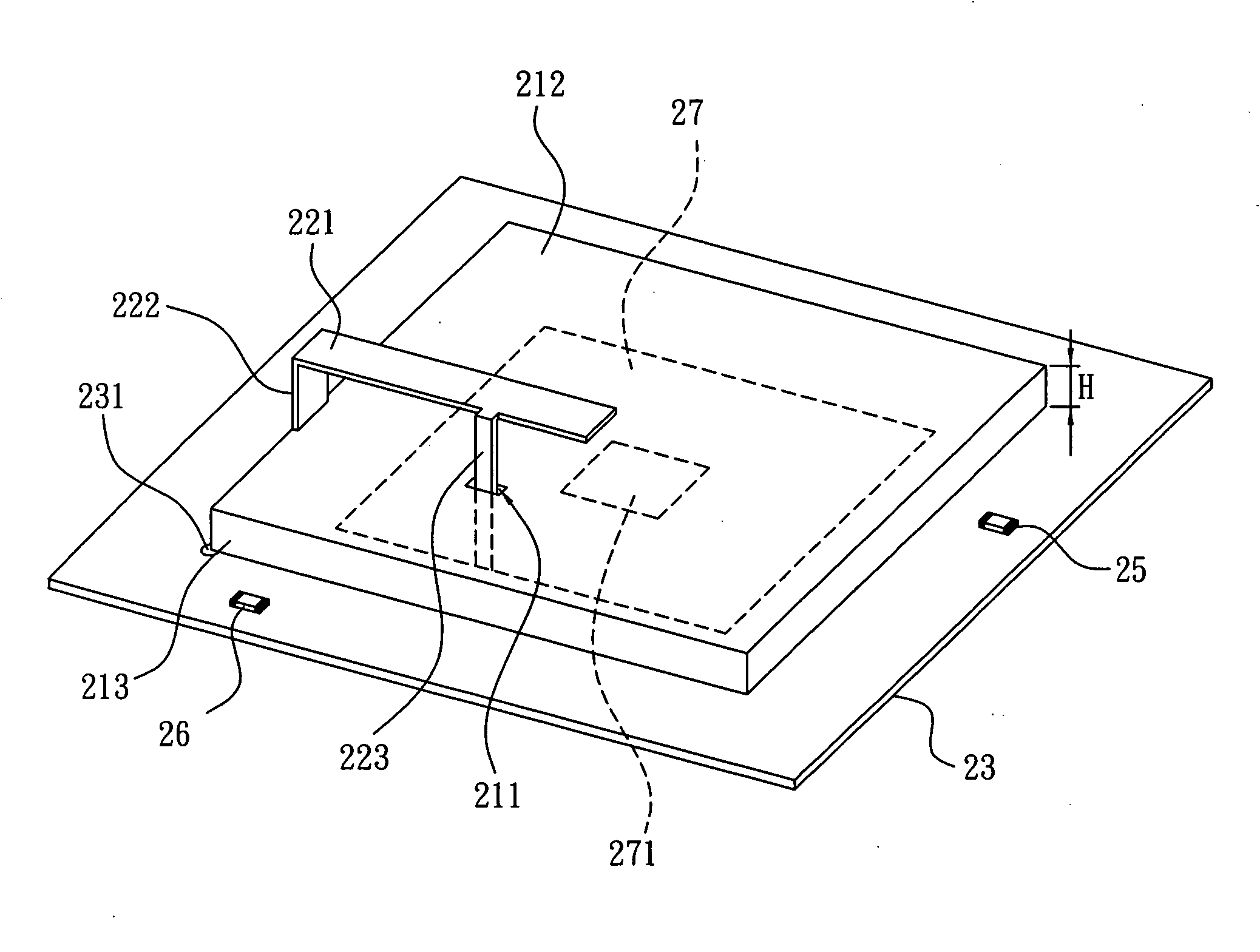
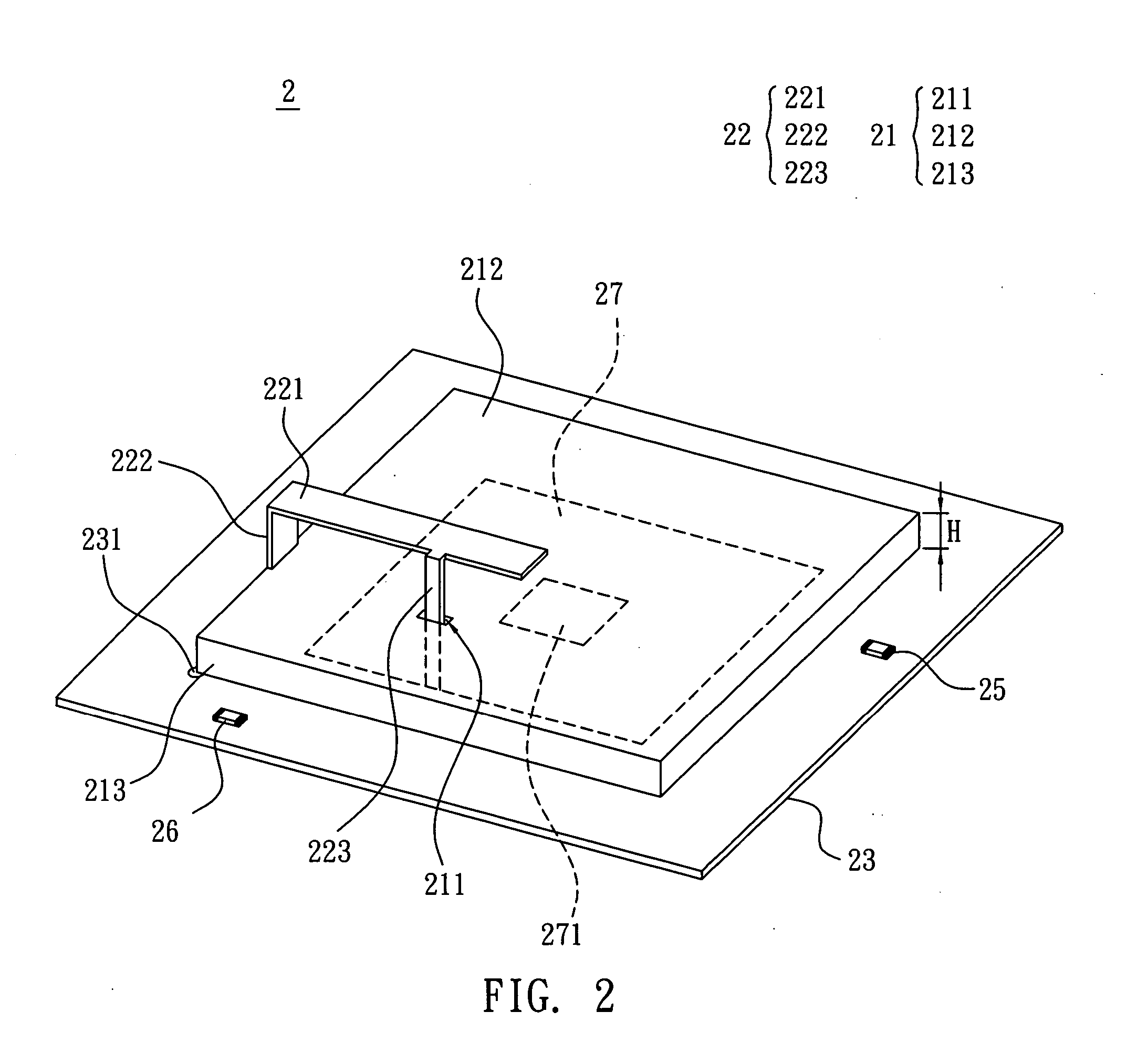
[0019] With reference to FIG. 2, a co-construction 2 according to a preferred embodiment of the invention includes a shield 21 and a first antenna 22. In the embodiment, the first antenna 22 and the shield 21 are integrally formed. The first antenna 22 can be an inverted-F antenna or a shorted patch antenna.

[0020] The shield 21 has a first hole 211. In the current embodiment, the shield 21 includes a major shielding portion 212 and a minor shielding portion 213. The minor shielding portion 213 is disposed annularly around the major shielding portion 212. The first hole 211 is located on the major shielding portion 212. For the minimized wireless transmission system, the minor 213 has a height H ranged from 1.5 mm to 40 mm.

[0021] In the embodiment, the shield 21 is fixed on a print...


PUM


Abstract

A co-construction with an antenna function and an EMI shielding function is electrically connected with a printed circuit board (PCB). A radio frequency circuit having a high frequency element is disposed on the PCB. The co-construction includes a shield and a first antenna. The shield has a first hole. The first antenna has a first radiator, a first ground point and a first feeding point. The first ground point is electrically connected to the first radiator and shield respectively. The first feeding point extends from one side of the first radiator and passes through the shield via the first hole to electrically connect to the radio frequency circuit of the PCB.

Description

BACKGROUND OF THE INVENTION [0001] 1. Field of Invention [0002] The invention relates to a co-construction and, in particular, to a co-construction with an antenna and an EMI shield. [0003] 2. Related Art [0004] In a wireless transmission system, the antenna is an important component used to transmit and / or receive the electromagnetic wave. In other words, if there were no antenna, the wireless transmission system could not transmit and receive information. Therefore, the antenna is an essential role in the wireless transmission system. [0005] However, the electromagnetic interference (EMI) is inevitable when the antenna works in cooperation with a high-frequency circuit. Thus, how to solve the EMI problem has become an important issue. The EMI means the induced electromagnetic energy in different frequencies or a band caused by intermittent or continuous voltage / current variations in a working electronic apparatus. In this case, the related circuit can emit the electromagnetic ener...

Claims


Application Information

Patent Timeline
Patent Type & Authority Applications(United States)
IPC IPC(8): H01Q1/38
CPCH01Q1/526H01Q21/24H01Q9/0421
Inventor LIU, I-RU
Owner ACCTON TECHNOLOGY CORPORATION
Why Eureka
Try Eureka