This helps you quickly interpret patents by identifying the three key elements:
Problems solved by technology
Method used
Benefits of technology
Benefits of technology
[0009]In view of the conventionally experienced disadvantages mentioned above, it is an object of the present invention to provide: a beam expanding optical element that, despite having a simple structure, operates with reduced color unevenness; a beam expansion method associated therewith; an image display apparatus provided with such a beam expanding optical element; and a head-mounted display provided with such an image display apparatus.
[0013]Here, the first and second holographic diffractive optical elements each have interference fringes with n different pitches (where n is a natural number equal to or greater than two) so as to diffract light of n different wavelengths at substantially equal angles. Thus, even when light of n different wavelengths is incident on the optical waveguide member, the emission pitch of the light emitted from the second holographic diffractive optical element to the outside is substantially equal among light of the n different wavelengths. Hence, with a simple structure involving a plurality of holographic diffractive optical elements bonded to a single optical waveguide member, it is possible to reduce color unevenness (color dispersion). In addition, the use of a single optical waveguide member contributes to low cost.
Problems solved by technology
This optical element can be used with no problem with light of a single color; when used with light of a wide wavelength width, however, it disadvantageously produces color unevenness (chromatic dispersion).
This produces color unevenness.
Thus, the optical element has a five-layer structure, a complicated one that makes the optical element extremely expensive.
Method used
Image
Click on the blue label to locate the original text in one second.
Reading with bidirectional positioning of images and text.
Examples
embodiment 1
[0031]An embodiment of the invention will be described below with reference to the accompanying drawings.
1. Structure of a Beam Expansion Optical Element
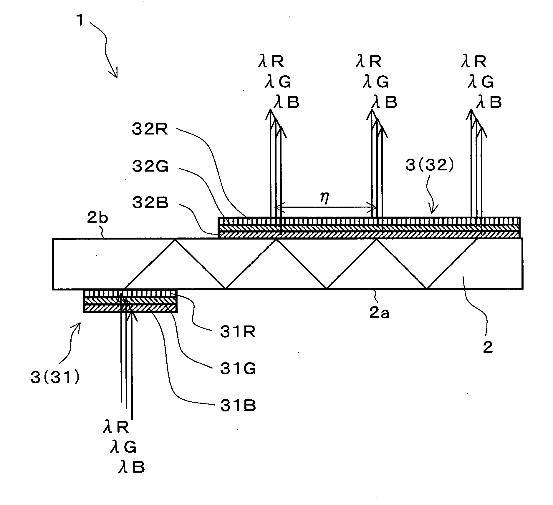
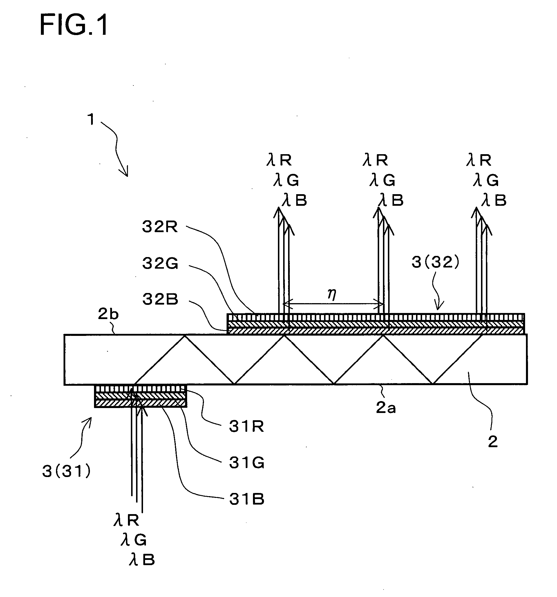
[0032]FIG. 1 is a cross-sectional view showing an outline of the structure of a beam expanding optical element 1 as a first embodiment of the invention. The beam expanding optical element 1 is an optical element that expands the beam diameter of the light incident thereon and then emits it. The beam expanding optical element 1 includes an optical waveguide member 2 and a plurality of volume-phase-type holographic diffractive optical elements 3.
[0033]In this embodiment, the optical waveguide member 2 is realized with a parallel plate; that is, the optical waveguide member 2 has two mutually opposite faces 2a and 2b, which have mutually parallel flat surfaces.
[0034]In this embodiment, the holographic diffractive optical elements 3 include two holographic diffractive optical elements, namely HOEs 31 and 32. In this embodiment, the HOEs...
embodiment 2
[0064]Another embodiment of the invention will be described below with reference to the accompanying drawings. In the following description, for the sake of convenience, such components and structures as are found also in Embodiment 1 are identified with common reference numerals and symbols, and no description thereof will be repeated.
[0065]FIG. 4 is a cross-sectional view showing an outline of the structure of a beam expanding optical element 1 as a second embodiment of the invention. The beam expanding optical element 1 of this embodiment differs from that of Embodiment 1 in that, here, the HOEs 31 and 32 constituting the holographic diffractive optical elements 3 are reflective.
[0066]In this embodiment, the hologram photosensitive material of which the HOEs 31 and 32 are formed is a single layer of a photopolymer that has interference fringes corresponding to three, namely R, G, and B, wavelengths recorded therein. That is, in this embodiment, in each of the HOEs 31 and 32, an i...
embodiment 3
[0076]Yet another embodiment of the invention will be described below with reference to the accompanying drawings. In the following description, for the sake of convenience, such components and structures as are found also in Embodiment 1 or 2 are identified with common reference numerals and symbols, and no description thereof will be repeated.
[0077]FIG. 6 is a perspective view showing an outline of the structure of a beam expanding optical element 1 as a third embodiment of the invention. In this embodiment, the holographic diffractive optical elements 3 provided in the beam expanding optical element 1 include, in addition to HOEs 31 and 32 just like those provided in Embodiment 1 or 2, a HOE 33. The HOE 33 is a third holographic diffractive optical element that diffracts the light diffracted by the HOE 31 and then traveling inside the optical waveguide member 2 such that the light is deflected toward where the HOE 32 is arranged. The HOE 33 is reflective, and is held on the face ...
PUM
Abstract
A first HOE and a second HOE are respectively arranged on two opposite faces of an optical waveguide member. The first HOE diffracts light incident from the outside on the optical waveguide member such that the light is then totally reflected inside the optical waveguide member and is thereby directed to the second HOE. The second HOE diffracts, according to the diffraction efficiency thereof, part of the light incident thereon after being guided inside the optical waveguide member such that this part of the light is then emitted to the outside substantially parallel to the light incident on the optical waveguide member, and the second HOE simultaneously totally reflects the rest of the light incident thereon. The second HOE repeats such emission and total reflection. The first and second HOEs each have interference fringes with n different pitches (where n is a natural number equal to or greater than two) to diffract light of n different wavelengths at substantially equal angles. Thus, even when light of n different wavelengths is incident on the optical waveguide member, the second holographic diffractive optical element emits it to the outside with substantially equal pitches for the light of the n different wavelengths.
Description
[0001]This application is based on Japanese Patent Application No. 2006-038819 filed on Feb. 16, 2006, the contents of which are hereby incorporated by reference.BACKGROUND OF THE INVENTION[0002]1. Field of the Invention[0003]The present invention relates to: a beam expanding optical element that expands the beam diameter of the light incident thereon and then emits it; a beam expansion method associated therewith; an image display apparatus provided with such a beam expanding optical element; and a head-mounted display (hereinafter also referred to as “HMD”) provided with such an image display apparatus.[0004]2. Description of Related Art[0005]There have conventionally been proposed various beam expanding optical elements that expand the beam diameter of the light incident thereon and then emit it. For embodiment, in the optical element disclosed in U.S. Pat. No. 6,580,529 B1, light incident on an optical waveguide member is diffracted and thereby reflected by three diffractive ele...
Claims
Application Information
Patent Timeline
Application Date:The date an application was filed.
Publication Date:The date a patent or application was officially published.
First Publication Date:The earliest publication date of a patent with the same application number.
Issue Date:Publication date of the patent grant document.
PCT Entry Date:The Entry date of PCT National Phase.
Estimated Expiry Date:The statutory expiry date of a patent right according to the Patent Law, and it is the longest term of protection that the patent right can achieve without the termination of the patent right due to other reasons(Term extension factor has been taken into account ).
Invalid Date:Actual expiry date is based on effective date or publication date of legal transaction data of invalid patent.

