Ceramic capacitor mounting structure and ceramic capacitor

a technology of ceramic capacitors and mounting structures, which is applied in the direction of final product manufacturing, furnaces, charge manipulation, etc., can solve the problem of limiting the degree of freedom in designing the substrate for mounting capacitors, and achieve the effect of reducing the degree of freedom, reducing the sound generated from the substrate, and increasing the capacity

Active Publication Date: 2007-08-16
TDK CORPARATION
View PDF9 Cites 29 Cited by
  • Summary
  • Abstract
  • Description
  • Claims
  • Application Information

AI Technical Summary

Benefits of technology

[0014]Preferably, the first terminal portion of the first metal terminal is parallel to the substrate and has a portion opposing the first capacitor connecting portion when seen in a direction orthogonal to the substrate. When the first capacitor connecting portion and the first terminal portion oppose each other, the first metal terminal has an elastic force, and can absorb vibrations of the ceramic capacitor. As a result, the sounding generated from the substrate can be reduced more.
[0015]Alternatively, it will be preferred if the first terminal portion of the first metal terminal is parallel to the substrate and has a portion opposing the first capacitor connecting portion when seen in a direction orthogonal to the substrate, and the second terminal portion of the second metal terminal is parallel to the substrate and has a portion opposing the second capacitor connecting po...

Problems solved by technology

This limits the degree of freedom in desi...

Method used


Image

  • Ceramic capacitor mounting structure and ceramic capacitor
  • Ceramic capacitor mounting structure and ceramic capacitor
  • Ceramic capacitor mounting structure and ceramic capacitor

Examples


first embodiment

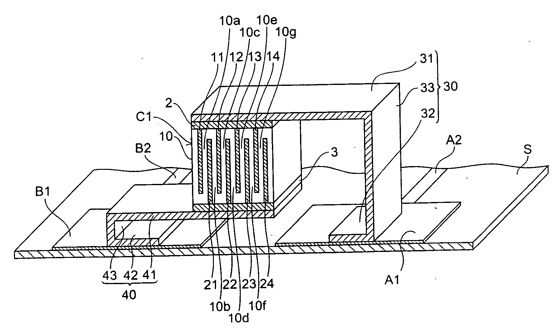
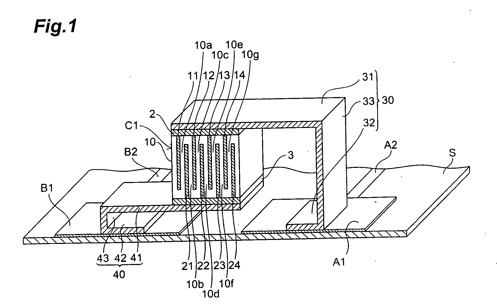
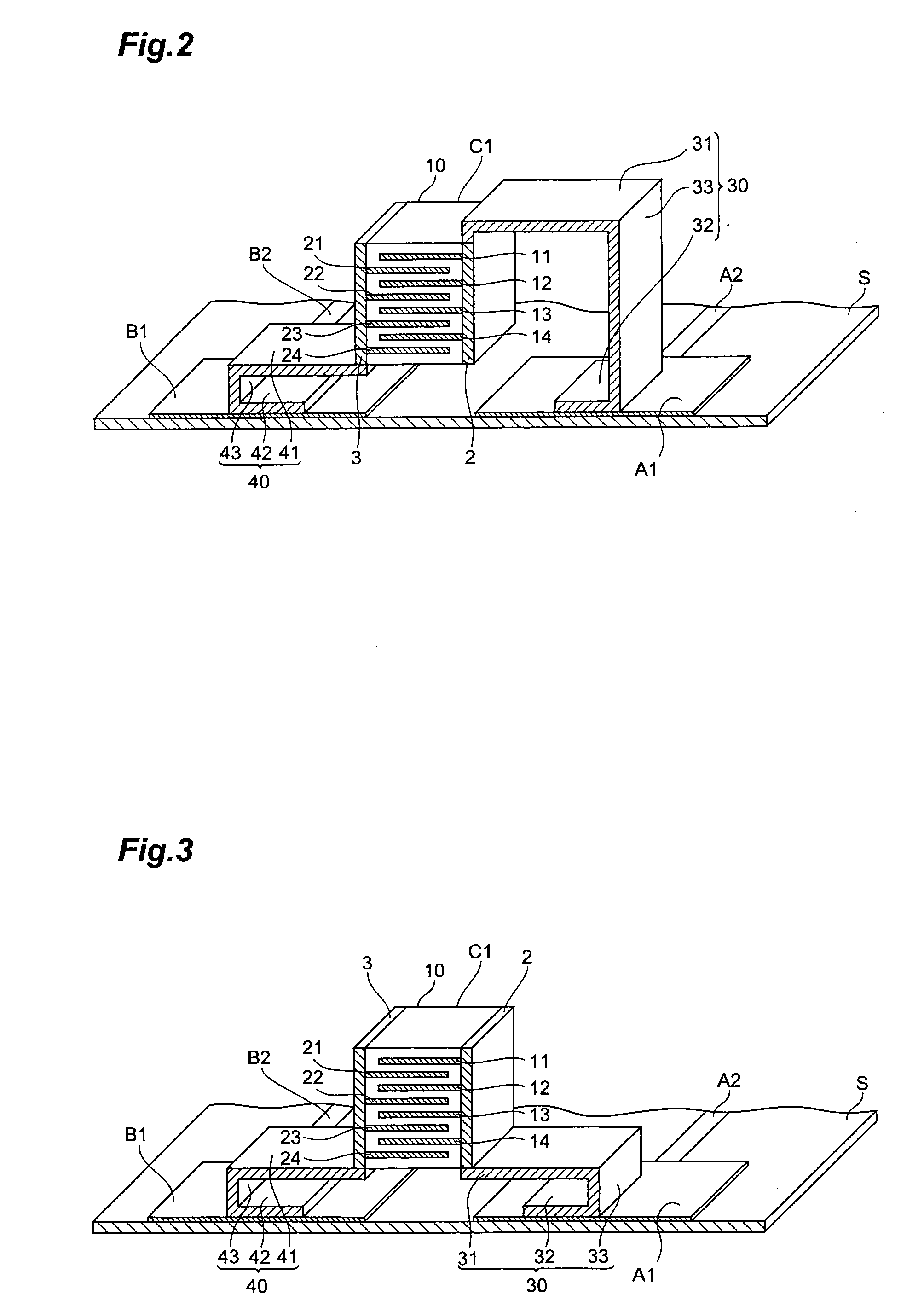
[0032]A ceramic capacitor mounting structure in accordance with a first embodiment will be explained with reference to FIG. 1. FIG. 1 is a cross-sectional perspective view showing a ceramic capacitor mounting structure in accordance with the first embodiment. FIG. 1 omits the hatching in the region corresponding to the ceramic within a ceramic sintered body 10.

[0033]In the ceramic capacitor mounting structure in accordance with the first embodiment, a ceramic capacitor C1 is mounted to a substrate S. A positive electrode land pattern A1 and a negative electrode land pattern B1 are formed on the substrate S. Leads A2 and B2 extend from the positive electrode land pattern (first land electrode) A1 and the negative electrode land pattern (second land electrode) B1, respectively.

[0034]The ceramic capacitor C1 comprises the ceramic sintered body 10, and first and second terminal electrodes 2, 3 which are formed on outer surfaces of the ceramic sintered body 10.

[0035]As shown in FIG. 1, t...

second embodiment

[0052]With reference to FIG. 4, a ceramic capacitor mounting structure in accordance with a second embodiment will be explained. The ceramic capacitor mounting structure in accordance with the second embodiment differs from the mounting structure for the ceramic capacitor C1 in accordance with the first embodiment in terms of the number of ceramic capacitors mounted to the substrate S. FIG. 4 is a cross-sectional perspective view showing the ceramic capacitor mounting structure in accordance with the second embodiment. FIG. 4 omits the hatching in the regions corresponding to the ceramics within the ceramic sintered bodies 10, 20.

[0053]In the ceramic capacitor mounting structure in accordance with the second embodiment, a plurality of (2 in this embodiment) ceramic capacitors C1, C2 are mounted to the substrate S. The ceramic capacitor C2 comprises a ceramic sintered body 20 and a plurality of (2 in this embodiment) terminal electrodes 4, 5 formed on two different outer surfaces of ...

third embodiment

[0068]A ceramic capacitor mounting structure in accordance with a third embodiment will be explained with reference to FIG. 5. The ceramic capacitor mounting structure in accordance with the third embodiment differs from the mounting structure for the ceramic capacitor C1 in accordance with the first embodiment in terms of the number of terminal electrodes connected to the substrate through metal terminals. FIG. 5 is a cross-sectional perspective view showing the ceramic capacitor mounting structure in accordance with the third embodiment. FIG. 5 omits the hatching in the region corresponding to the ceramic within a ceramic sintered body 10.

[0069]In the ceramic capacitor mounting structure in accordance with the third embodiment, a ceramic capacitor C1 is mounted to a substrate S.

[0070]A first terminal electrode 2 of the ceramic capacitor C1 is electrically connected to a positive electrode land pattern A1 on the substrate S through a first metal terminal 30 connected onto the subst...


PUM


Abstract

A ceramic capacitor comprises a ceramic sintered body, and first and second terminal electrodes formed on outer surfaces of the ceramic sintered body. The first terminal electrode is electrically connected to a land formed on a substrate through a first metal terminal. The first metal terminal has a first capacitor connecting portion mechanically connected to the first terminal electrode, a first terminal portion mechanically connected to the land, and a first intermediate portion electrically connecting the first capacitor connecting portion and the first terminal portion to each other. The first capacitor connecting portion of the first metal terminal is parallel to the substrate.

Description

BACKGROUND OF THE INVENTION[0001]1. Field of the Invention[0002]The present invention relates to a ceramic capacitor mounting structure and a ceramic capacitor.[0003]2. Related Background Art[0004]When a voltage is applied to a ceramic capacitor, a mechanical distortion having a magnitude corresponding to the applied voltage occurs in the ceramic sintered body because of the electrostrictive effect of the ceramic. Consequently, a vibration occurs in the ceramic capacitor when an AC voltage is applied thereto. Such a vibration propagates to a substrate mounting the ceramic capacitor, which causes the problem of sounding in the substrate.[0005]Therefore, for reducing the sounding of the substrate, a structure in which a pair of ceramic capacitors are mounted symmetrical to each other on the front and rear faces of the substrate with the substrate interposed therebetween has been considered (see Patent Document 1). The mounting structure described in Patent Document 1 mounts a pair of ...

Claims


Application Information

Patent Timeline
IPC IPC(8): H01G4/228
CPCH01G2/065H01G4/232H01G4/30H05K2201/10818H05K2201/10469H05K2201/10651H05K3/3426Y02P70/50C21B7/14C21B7/06F27D3/145F27D2021/0085
Inventor TOGASHI, MASAAKIUSHIODA, KENTARO
Owner TDK CORPARATION
Why Eureka
Try Eureka