Backlight module

a backlight module and backlight technology, applied in the field of backlight modules, can solve the problems of inconvenient use of limited effect of elimination of dark zones, and inability to achieve compact electronic products such as handheld displays, and achieve the effects of good uniformity, high luminance efficiency, and good uniformity

Inactive Publication Date: 2007-08-16
WINTEK CORP
View PDF10 Cites 60 Cited by
  • Summary
  • Abstract
  • Description
  • Claims
  • Application Information

AI Technical Summary

Benefits of technology

[0012]Through the design of the invention, since the light emitting surface of the bar member is bent toward the light reflecting surface of the bar member, the bar member is shaped as two trapezoidal bodies positioned side by side to provide more space for light propagation. Thus, the emitting light of the point light source is fully utilized and evenly distributed inside the light guide plate to result in high luminance efficiency and good unifo

Problems solved by technology

Typically, a linear light source such as a cold-cathode fluorescent lamp (CCFL) is often used in a backlight module; however, it is bulky and thus not suitable for a compact electronic product such as a handheld display.
However, this approach has limited e

Method used


Image

  • Backlight module
  • Backlight module
  • Backlight module

Examples


Embodiment Construction

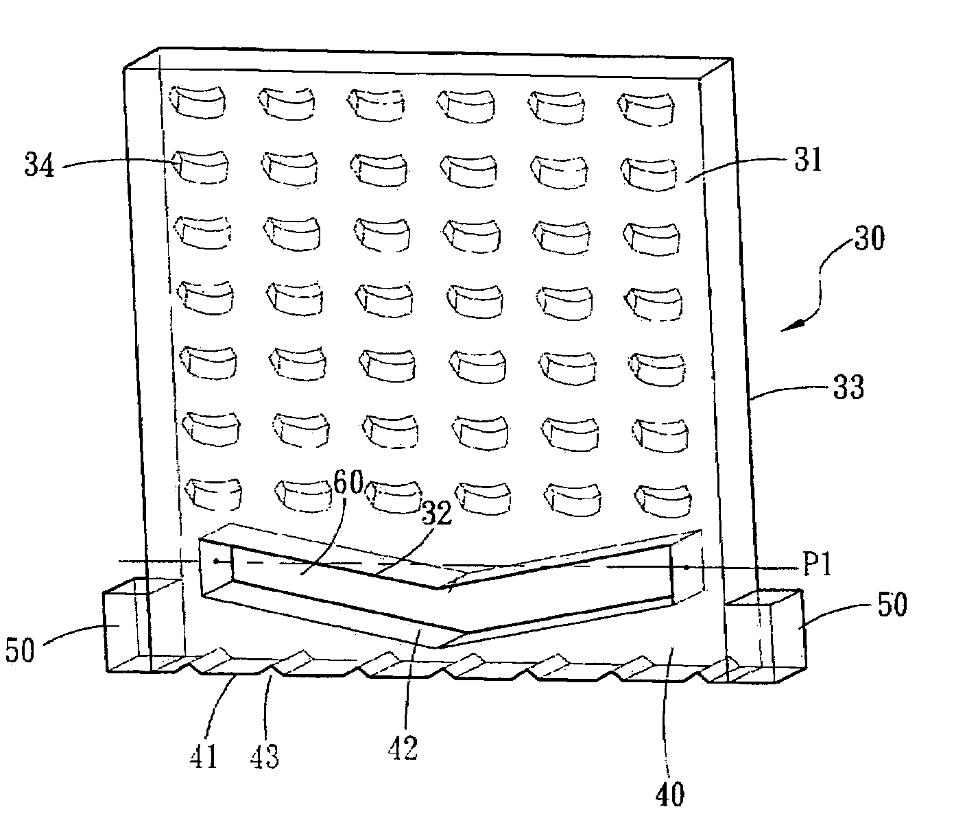
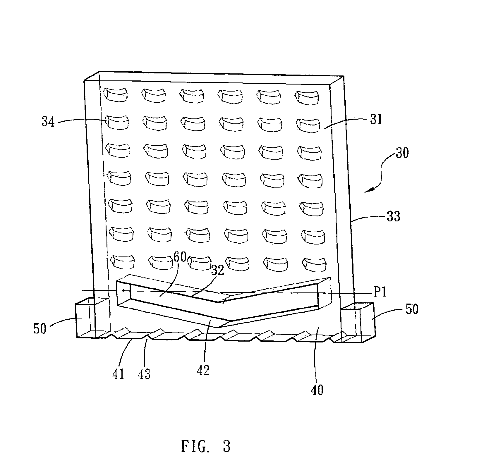
[0025]FIG. 3 shows a schematic diagram illustrating a backlight module according to an embodiment of the invention. As shown in FIG. 3, the backlight module having a point light source includes a light guide plate 30, a bar member 40 and two light emitting diodes 50. The light guide plate 30 has a light receiving surface 32, a light emitting surface 31 perpendicular to the light-receiving surface 32, and a bottom surface 33 opposite to the light emitting surface 31. A plurality of light deflecting elements 34 for diffusing light transmitted into the light guide plate 30 are formed on either the light emitting surface 31 or the bottom surface 33, or both. The emitting light of the light emitting diodes 50 are confined in the light guide plate 30 and diffused by the light deflecting elements 34 to allow for surface emission radiated from the light emitting surface 31 of the light guide plate 30. The light deflecting elements 34 may be grooves or notches formed on the plate surface.

[00...


PUM


Abstract

A backlight module includes a light guide plate, a bar member, and two point light sources. The bar member is connected to one side of the light guide plate with a slot being formed between them. The bar member has a light emitting surface facing the light receiving surface of the light guide plate and a light reflecting surface opposite to the light emitting surface, and the light emitting surface and the light receiving surface are spaced apart from each other by the slot. The light receiving surface of the light guide plate and the light emitting surface of the bar member are both bent toward or away from the light reflecting surface.

Description

BACKGROUND OF THE INVENTION[0001](a) Field of the Invention[0002]The invention relates to a backlight module, and particularly to a backlight module in which a point light source is converted into a linear light source having improved light utilization efficiency.[0003](b) Description of the Related Art[0004]Typically, a linear light source such as a cold-cathode fluorescent lamp (CCFL) is often used in a backlight module; however, it is bulky and thus not suitable for a compact electronic product such as a handheld display. In contrast, a point light source such as a light emitting diode (LED) is fit for such kind of electronic product due to its small size.[0005]FIG. 1 shows a schematic diagram illustrating a conventional backlight module using a point light source. Referring to FIG. 1, two light emitting diodes 11 are positioned next to one side of a light guide plate 10 and spaced apart from each other a predetermined distance. As to a point light source, the relationship betwee...

Claims


Application Information

Patent Timeline
IPC IPC(8): F21V7/04
CPCG02B6/0036G02B6/0018
Inventor CHEN, PING-YENGHUANG, KUO-JUI
Owner WINTEK CORP
Why Eureka
Try Eureka