Eureka AIR delivers breakthrough ideas for toughest innovation challenges, trusted by R&D personnel around the world.

Method and apparatus for channel state information generation in a DVB-T receiver

Active Publication Date: 2007-08-16
MEDIATEK INC
View PDF8 Cites 36 Cited by
  • Summary
  • Abstract
  • Description
  • Claims
  • Application Information

AI Technical Summary

Benefits of technology

[0007] To solve the foregoing drawbacks in the prior arts, it is an objective of the present invention to provide a method and apparatus for channel state information (CSI) generation capable of exhibiting good performance in both the static and mobile communication environments.
[0008] Another objective of the present invention is to provide a method and apparatus for channel state information generation in a DVB-T receiver that can perform well with both co-interference and AWGN. In addition, the present method also has the advantage of quick convergence in initialization when the system is suffering large delay spread of channel impulse response.

Problems solved by technology

However, it does not exhibit good performance in a channel with co-channel interference, which is the real environments where the OFDM signals are broadcasted.
For example, some inherent analog TV channel may be mixed with the DVB-T (Digital Video Broadcasting Terrestrial) channel and co-channel interference is generated as a result.
In such case, using magnitude of a channel frequency response may result in an unreliable CSI caused by severe interference to those sub-carriers.
However, there are two drawbacks of this method.
First, an inaccuracy of SNR estimation may cause additional degradation in AWGN environment.
Second, a temporal-averaged SNR does not respond quickly to the channel change in mobile environment.
However, an unpredictable co-channel interference comes as an unavoidable consequence of channel reuse, which makes the assumption of flat noise incorrect.
However, the drawback of this method is the bad performance in mobile channel.

Method used


Image

  • Method and apparatus for channel state information generation in a DVB-T receiver
  • Method and apparatus for channel state information generation in a DVB-T receiver
  • Method and apparatus for channel state information generation in a DVB-T receiver

Examples


Embodiment Construction

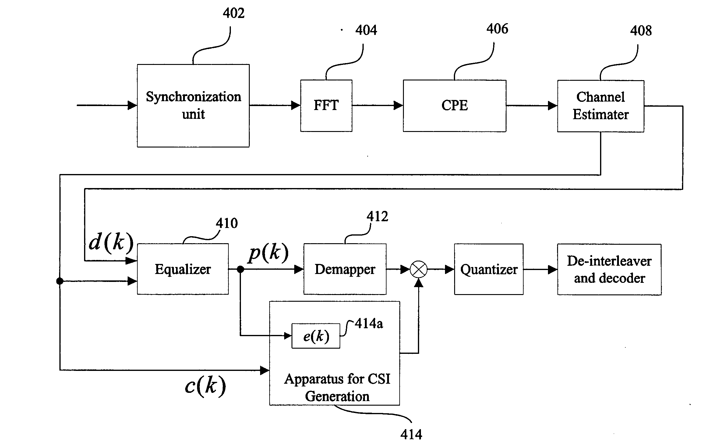
[0031] Please refer to FIG. 4, which is a block diagram showing a portion of a DVB-T receiver in an embodiment according to the present invention. The DVB-T receiver at least comprises a channel estimator 408, an equalizer 410, a demapper 412 and an apparatus for channel state information (CSI) generation 414 including an error signal calculation unit 414a. A synchronization unit 402 first executes the time and frequency synchronization and removes the Guard-Interval of the OFDM symbols, and then the processed OFDM signals are transmitted into a FFT block 404 to be transformed from the time domain into the frequency domain. A Common Phase Error (CPE) block 406 is employed to compensate the phase noise. The channel estimator 408 estimates the channel response signal c(k) according to the pilot information of the sub-carrier and transmits the original signal d(k) and the channel response signal c(k) to the equalizer 410. The original signal d(k) is the signal directly passing through ...


PUM


Abstract

A method and apparatus for channel state information generation in a DVB receiver. The present invention comprises: obtaining the magnitude of an error signal and a channel response signal of a sub-carrier; combining the magnitude of the error signal and the magnitude of the channel response signal of each sub-carrier; averaging the magnitudes of the error signals for sub-carriers; calculating the ratio of the channel response signal and the average of the magnitudes of the error signals; and generating a channel state information according to the ratio for the sub-carrier of the OFDM symbol. The method exhibits good performance in either a channel with the AWGN or with co-channel interference, and provides a quick convergence in initialization for the receiver to mitigate the channel impulse response.

Description

FIELD OF THE INVENTION [0001] The present invention generally relates to a method and apparatus for channel state information generation, and more particularly to a method and apparatus for channel state information generation in a Digital Video Broadcast Terrestrial (DVB-T) receiver. BACKGROUND OF THE INVENTION [0002] In an Orthogonal Frequency Division Multiplexing (OFDM) modulation system employed in a DVB-T transmitter and receiver system, the channel state information (CSI) is applied to increase the reliability of each sub-carrier so that the Bit Error Rate (BER) after a channel decoder can be decreased. It is significantly important in a frequency selective fading channel, and methods generating CSI have been disclosed. Generally, these channel state informations are defined based on a magnitude of a channel frequency response signal in each sub-carrier or an SNR (signal to noise ratio) of each sub-carrier. The former method can have good performance when the noise brought to...

Claims


Application Information

Patent Timeline
IPC IPC(8): H04K1/10
CPCH04L25/0232H04L27/2647H04L25/025
Inventor YANG, SHUN-AN
Owner MEDIATEK INC
Why Eureka
Eureka Blog
Learn More