Developing Device and Toner Cartridge

a technology of developing device and toner cartridge, which is applied in the direction of instruments, electrographic process equipment, optics, etc., can solve the problems of inability to uniformly adhere inability to return toner cartridges from the developing chamber inability to achieve uniform adhesion of toner to the developing roller at a suitable thickness, so as to prevent the accumulation of poor quality toner inside the developing chamber

Active Publication Date: 2007-08-16
BROTHER KOGYO KK
View PDF8 Cites 62 Cited by
  • Summary
  • Abstract
  • Description
  • Claims
  • Application Information

AI Technical Summary

Benefits of technology

[0009]According to the above technology, toners are circulated between the developing device and the toner cartridge. By causing the toners to circulate, the stagnation and accumulation of poor quality toners occur inside the developing chamber can be prevented. In addition, fresh toners can be uniformly adhered across the entire supply roller.

Problems solved by technology

When toners inside the developing chamber are not in a densely packed state, the toners will not adhere uniformly to the developing roller at a suitable thickness.
This is because there will be an effect on the developing roller, due to the fact that toners will not uniformly adhere to the supply roller.
When the other side wall opening is placed in a high position, it will become difficult for the toners to be returned from the developing chamber to the toner cartridge.
In the aforementioned conventional technology, the toners can neither be uniformly adhered to the developing roller at a suitable thickness, nor can it be smoothly circulated.

Method used


Image

  • Developing Device and Toner Cartridge
  • Developing Device and Toner Cartridge
  • Developing Device and Toner Cartridge

Examples


first embodiment

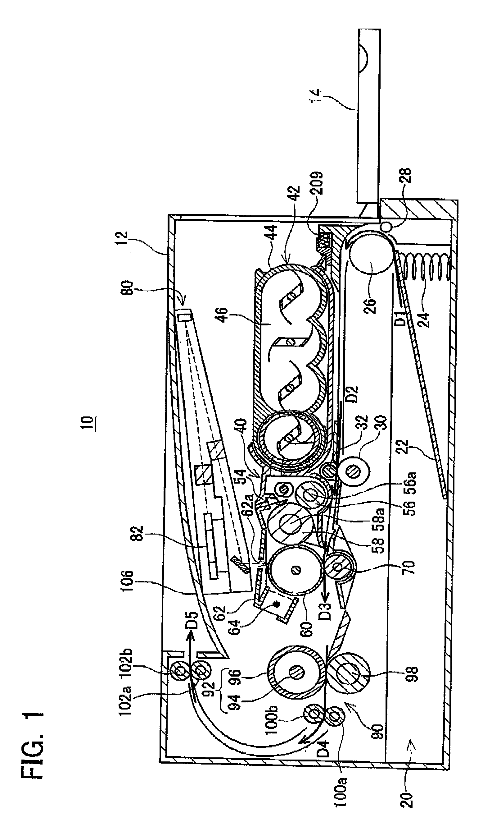
[0049]An embodiment of the present invention will be described with reference to the drawings. FIG. 1 is an overall vertical cross-section of a laser printer 10 of the present embodiment. The laser printer 10 will be hereinafter simply referred to as the “printer 10”.

(Overall Construction of the Laser Printer)

[0050]First, the overall construction of the laser printer 10 will be briefly explained.

(Construction of the Casing)

[0051]The printer 10 has a casing 12. The casing 12 comprises a plurality of plate-shaped members. The casing 12 has a door 14. In FIG. 1, the door 14 is shown in the open state. In this state, a toner cartridge 42 described below can be replaced. When the door 14 is pivoted in the counterclockwise direction from the state shown in FIG. 1, the casing 12 will be closed.

[0052]The printer 10 has a paper supply device 20, a developing device 40, a photoreceptor 60, a transferring device 70, an exposure device 80, a toner fixing device 90, and the like. The devices 20,...

second embodiment

[0164]Here, the points that differ from the first embodiment will be described. FIG. 14 shows a front view of a toner cartridge 342 of the present embodiment (the same view as shown in FIG. 7 of the first embodiment).

[0165]Like with the first embodiment, a pair of case openings 344a, 344b is formed in a front surface 180 of a case main body 344. The case feed opening 344a is constructed in the same way as in the first embodiment. The case return opening 344b is inclined downward and to the left. In other words, the end portion A1 on the far side from the case feed opening 344a is located below the end portion B1 on the near side to the case feed opening 344a.

[0166]The sponge 182b located around the case return opening 344b has an opening that is the same shape as the case return opening 344b (reference number omitted). The opening of the sponge 182b faces the case return opening 344b.

[0167]FIG. 15 shows a front view of a developing device 340 of the present embodiment (the same vi...

third embodiment

[0170]FIG. 16 shows a front view of a toner cartridge 442 of the present embodiment (the same view as shown in FIG. 7 of the first embodiment).

[0171]With a case ret opening 444b formed in the front surface 180 of a case main body 444, the right half 444b-1 extends along the horizontal direction, and the left half 444b-2 is inclined downward and to the left. In this case as well, the case return opening 444b can be said to be inclined downward and to the left. The end portion A3 on the far side from a case feed opening 444a is located below the end portion B3 on the near side to the case feed opening 444a.

[0172]FIG. 17 shows a front view of a developing device 440 of the present embodiment (the same view as shown in FIG. 11 of the first embodiment).

[0173]With a side wall return opening 422b formed in a side wall 422, the left half 422b-1 extends along the horizontal direction, and the right half 422b-2 is inclined downward and to the right. In this case as well, the side wall return...


PUM


Abstract

A toner cartridge is to be attached to a developing device. The developing device is provided with a developing roller comprising a rotational axis extending along a horizontal direction, a first casing, and a first transporting member. The first casing includes a developing chamber for accommodating the toner to be supported by the developing roller, a first feed opening for feeding the toner from the toner cartridge to the developing chamber, and a first return opening for returning the toner from the developing chamber to the toner cartridge. The first transporting member is located within the developing chamber. The first transporting member transports the toner within the developing chamber from the first feed opening to the first return opening. The first feed opening and the first return opening are offset along the horizontal direction. The first feed opening is located higher the first return opening.

Description

CROSS-REFERENCE TO RELATED APPLICATION[0001]This application claims priority to Japanese Patent Application No. 2006-035443 filed on Feb. 13, 2006, the contents of which are hereby incorporated by reference into the present application.BACKGROUND OF THE INVENTION[0002]1. Field of the Invention[0003]The present invention relates to technology for using toner to develop an electrostatic latent image formed on a photoreceptor. More particularly, the present invention relates to a toner cartridge that accommodates toners and a developing device to which this is to be attached.[0004]2. Description of the Related Art[0005]An image forming device (e.g., a laser printer) having a photoreceptor uses a developing device. A toner cartridge is attached to the developing device. A standard developing device comprises a casing, a supply roller, and a developing roller. The casing has a space for housing the toner cartridge, and a developing chamber that communicates with the space. The supply rol...

Claims


Application Information

Patent Timeline
Patent Type & Authority Applications(United States)
IPC IPC(8): G03G15/08
CPCG03G15/0822G03G15/0896G03G2215/0802G03G15/0877G03G2215/0838G03G15/0875G03G15/0886G03G2215/0822
Inventor SATO, SHOUGO
Owner BROTHER KOGYO KK
Why Eureka
Try Eureka