Composite firearm barrel

a composite and firearm barrel technology, applied in the field of composite firearm barrels, can solve the problems of cumbersome carrying of steel-barreled firearms for long periods of time or to hold steady, high manufacturing cost of barrels, and heavy weight of steel-barreled firearms, and achieves efficient and economical manufacturing, superior and strong bond

Inactive Publication Date: 2007-08-23
STURM RUGER & CO INC
View PDF31 Cites 32 Cited by
  • Summary
  • Abstract
  • Description
  • Claims
  • Application Information

AI Technical Summary

Benefits of technology

[0004] An improved composite barrel and novel method for forming the same is provided that overcomes the foregoing shortcomings of known composite barrels. In a preferred embodiment, a composite barrel according to principles of the present invention is made by forging which provides a superior and strong bond between the different barrel components in contrast to the foregoing known fabrication techniques. The novel use of the forging method described herein integrates well with existing fabrication processes normally employed in a firearms factory to produce barrels. Therefore, additional and / or more complex fabrication steps and equipment are avoided which advantageously results in efficient and economical manufacturing in contrast to known methods. A composite barrel and method of manufacture as described herein may be utilized for both long barrel rifles and short barrel pistols, with equal advantage in either application.

Problems solved by technology

But barrels made of entirely steel tend to be heavy, which may make steel-barreled firearms cumbersome to carry for long periods of time or to hold steady during shooting competitions.
These barrels may be expensive to manufacture and the thinly coated bores surfaces may wear away over time.
Joining the multiple components together to form a secure bond capable of withstanding repeated firearm discharges, however, has been problematic.
These production techniques may result in composite barrels that may separate over repeated cycles of discharging a firearm due to inadequate bonding or coupling between the inner tubes and outer sleeves or shells.
Some known designs may also require multiple fabrication steps and be labor intensive to produce, thereby sometimes making manufacture of these conventional composite barrels complicated and expensive.

Method used


Image

  • Composite firearm barrel
  • Composite firearm barrel
  • Composite firearm barrel

Examples


Embodiment Construction

[0022] In order that the invention may be understood, a preferred embodiment, which is given by way of example only, will now be described with reference to the drawings. The preferred embodiment is described for convenience with reference and without limitation to a firearm barrel for a rifle. However, the principles disclosed herein may be used with equal advantage for a pistol or handgun. According, the invention is not limited in this respect. Moreover, the process for manufacturing composite material parts described herein may equally be employed for making light-weight components other than firearm barrels where weight and manufacturing savings are advantageous, such as in the aerospace industry. Accordingly, the preferred process described herein to make composite articles is not limited to firearm barrel production alone.

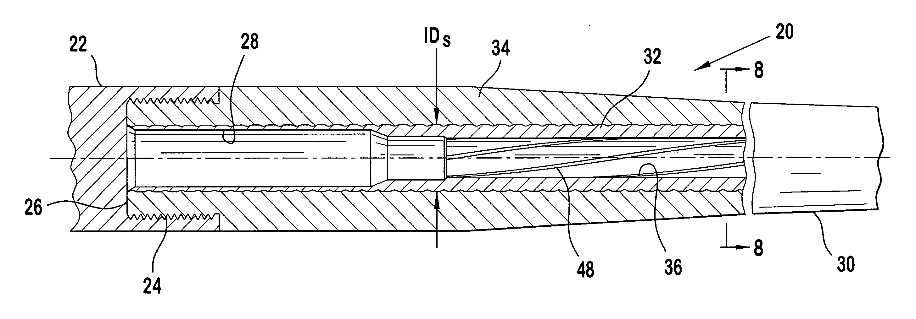
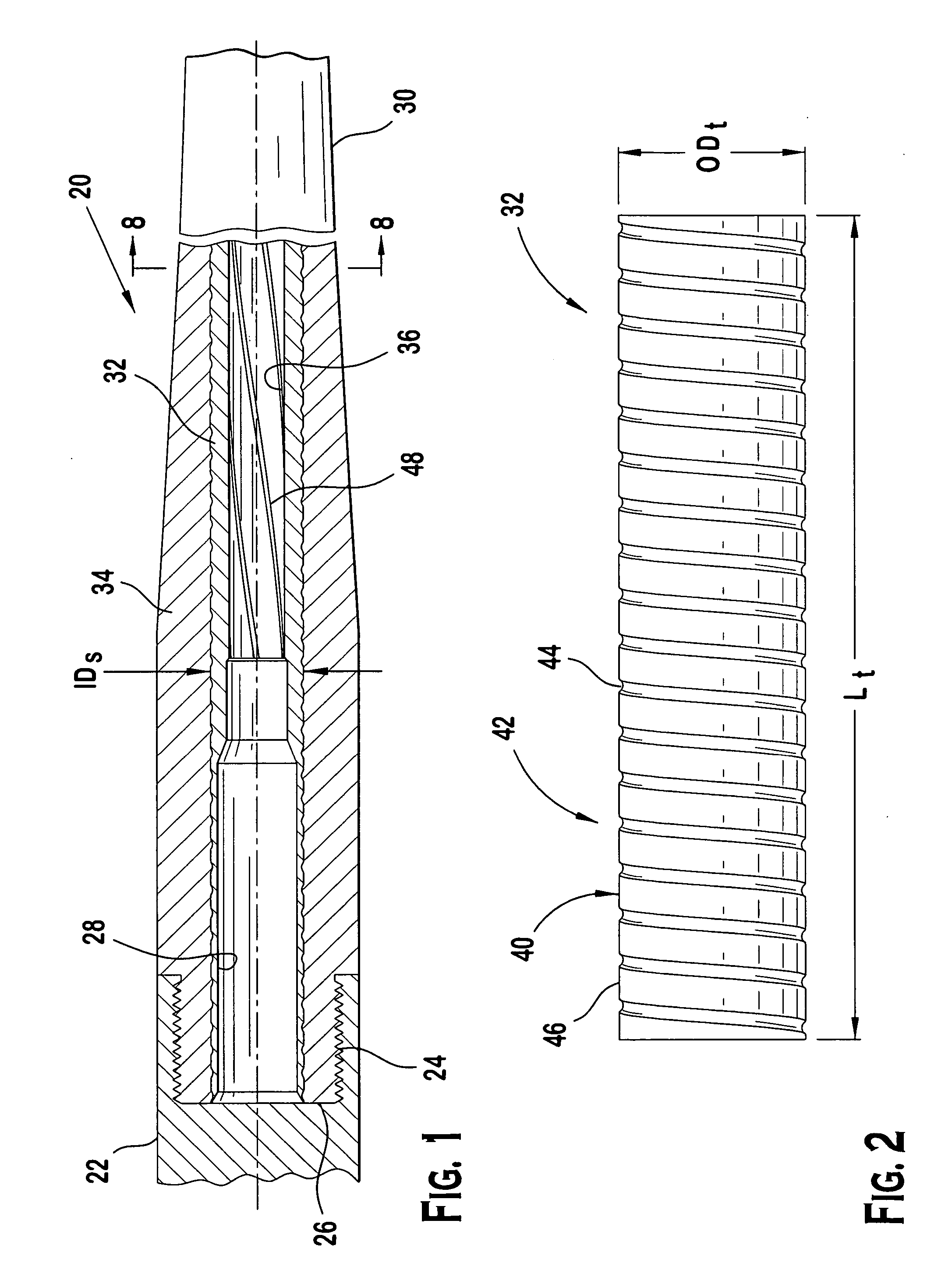
[0023] Referring now to FIG. 1 which shows a cross-section of a portion of a firearm, a firearm formed according to principles of the present invention in ...


PUM

PropertyMeasurementUnit
widthaaaaaaaaaa
widthaaaaaaaaaa
angleaaaaaaaaaa

Abstract

A composite barrel for a firearm and method for forming by forging. The barrel includes at least two materials joined together by forging. In a preferred embodiment, at least one material is preferably lighter in weight than the other material. The barrel may include an inner tube and an outer sleeve. The inner tube defines a bore that provides a bullet path and in one embodiment may be made of steel or alloys thereof. The outer sleeve surrounds the inner tube and in some embodiments may be made of aluminum, titanium, or alloys of either thereof. The tube preferably includes an exterior surface containing recessed areas therein for receiving material displaced from the outer sleeve by the forging process. The preferred barrel forming method generally may include inserting the tube into the sleeve, striking an outer surface of the sleeve, and deforming the sleeve to force material to flow into the recessed exterior surface of the tube to bond the tube and sleeve together. The method of forming may be used to produce long and short barrels for rifles and handguns respectively, and more broadly to produce other composite components unrelated to firearms.

Description

BACKGROUND OF THE INVENTION [0001] The present invention generally relates to firearms, and more particularly to an improved composite firearm barrel. [0002] The barrel of a firearm is in essence a pressure vessel that is subjected to heat and forces of combustion generated by igniting a cartridge powder charge when the firearm is discharged. Accordingly, steel has been the material of choice for firearm barrels because its mechanical properties allow it to repeatedly withstand numerous cycles of discharging the firearm. But barrels made of entirely steel tend to be heavy, which may make steel-barreled firearms cumbersome to carry for long periods of time or to hold steady during shooting competitions. One attempted solution to produce lighter barrels has been to use aluminum barrels provided with hard-coated or plated bore surfaces for the bullet path. These barrels may be expensive to manufacture and the thinly coated bores surfaces may wear away over time. Composite firearm barre...

Claims


Application Information

Patent Timeline
Patent Type & Authority Applications(United States)
IPC IPC(8): F41A21/00
CPCF41A21/02Y10T29/49934F41A21/04F41A19/02F41A21/18F41A21/20
Inventor BRIGGS, VERNON R.
Owner STURM RUGER & CO INC
Why Eureka
Try Eureka