Pull bar screen apparatus and system

a technology of pull bar and screen, which is applied in the direction of shutters/movable grilles, insect protection, door/window protective devices, etc., can solve the problems of reducing the overall quality and structural integrity affecting the service life of the fixed frame screen, and affecting the service life of the retractable screen product, etc., to achieve the elimination of the need for high frequency welding

Inactive Publication Date: 2007-08-23
HORVATH LOUIS
View PDF22 Cites 16 Cited by
  • Summary
  • Abstract
  • Description
  • Claims
  • Application Information

AI Technical Summary

Benefits of technology

[0028] One advantage of the invention is that screen material is connected directly to a pull bar.
[0029] Another advantage of the invention is that the pull bar of the pull bar screen is connected directly to the screen through frictional lock bars.
[0030] Another advantage of the invention is that the need for high frequency welding is eliminated.
[0031] Another advantage of the invention is that it eliminates the need for vinyl strip extrusion.
[0032] Another advantage of the invention is that the pultruded pull-bar can take place of presently available pull-bars without necessitating modification of the existing pull-bar system, thereby allowing retrofitting of existing systems.
[0033] Another advantage of the invention is that it can be implemented as a new system.

Problems solved by technology

The fixed frame screens typically represent perpetual maintenance problems because they are frail.
In manufacturing retractable screens, there are several flaws that reduce the overall quality and structural integrity of the retractable screen product.
In general, it is appreciated that imperfect positioning of the unsupported sheet of screen often occurs.
In addition, there are uneven expansion factors between the screen and the strip thereby causing unsightly wave patterns in the screen.

Method used


Image

  • Pull bar screen apparatus and system
  • Pull bar screen apparatus and system
  • Pull bar screen apparatus and system

Examples


Embodiment Construction

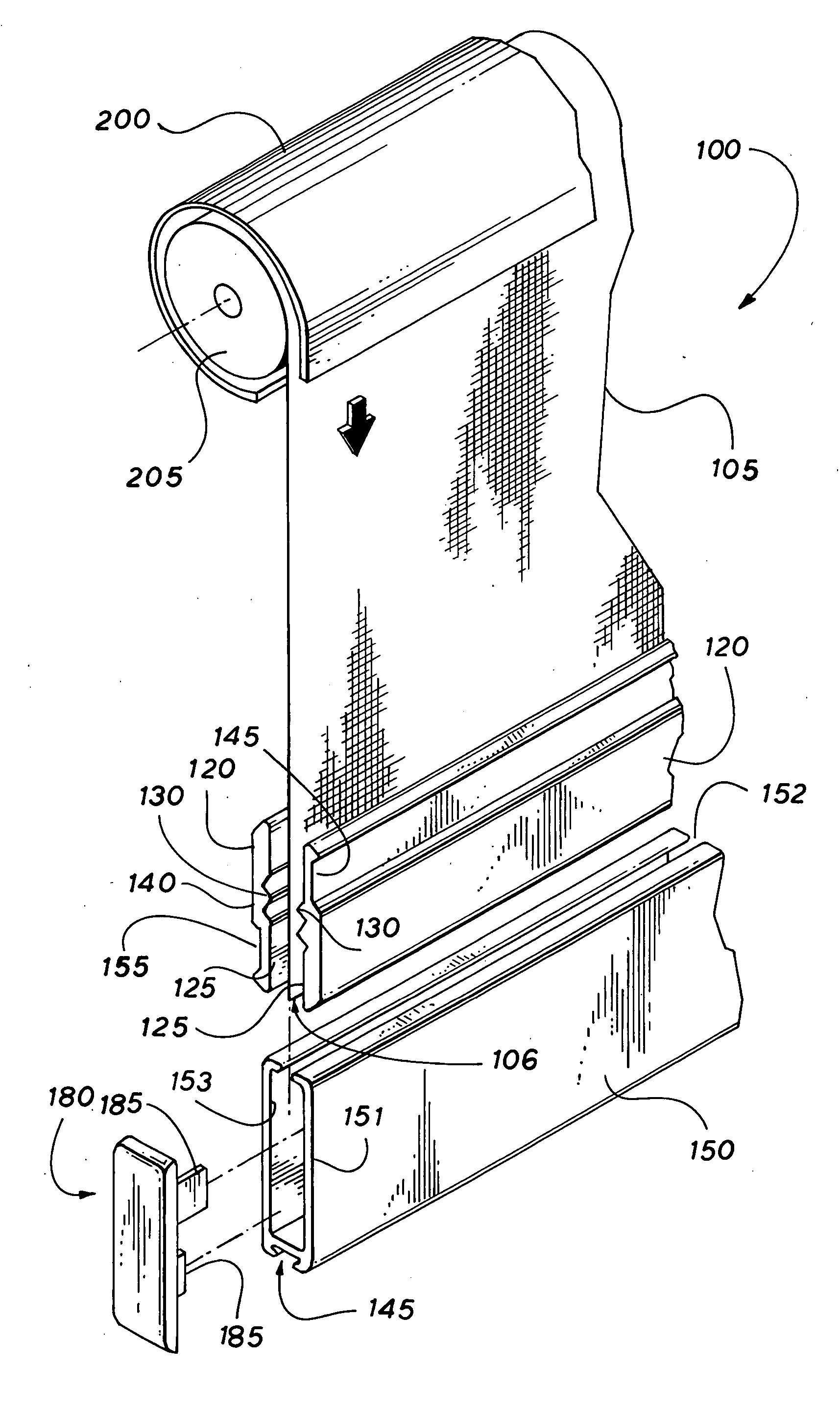
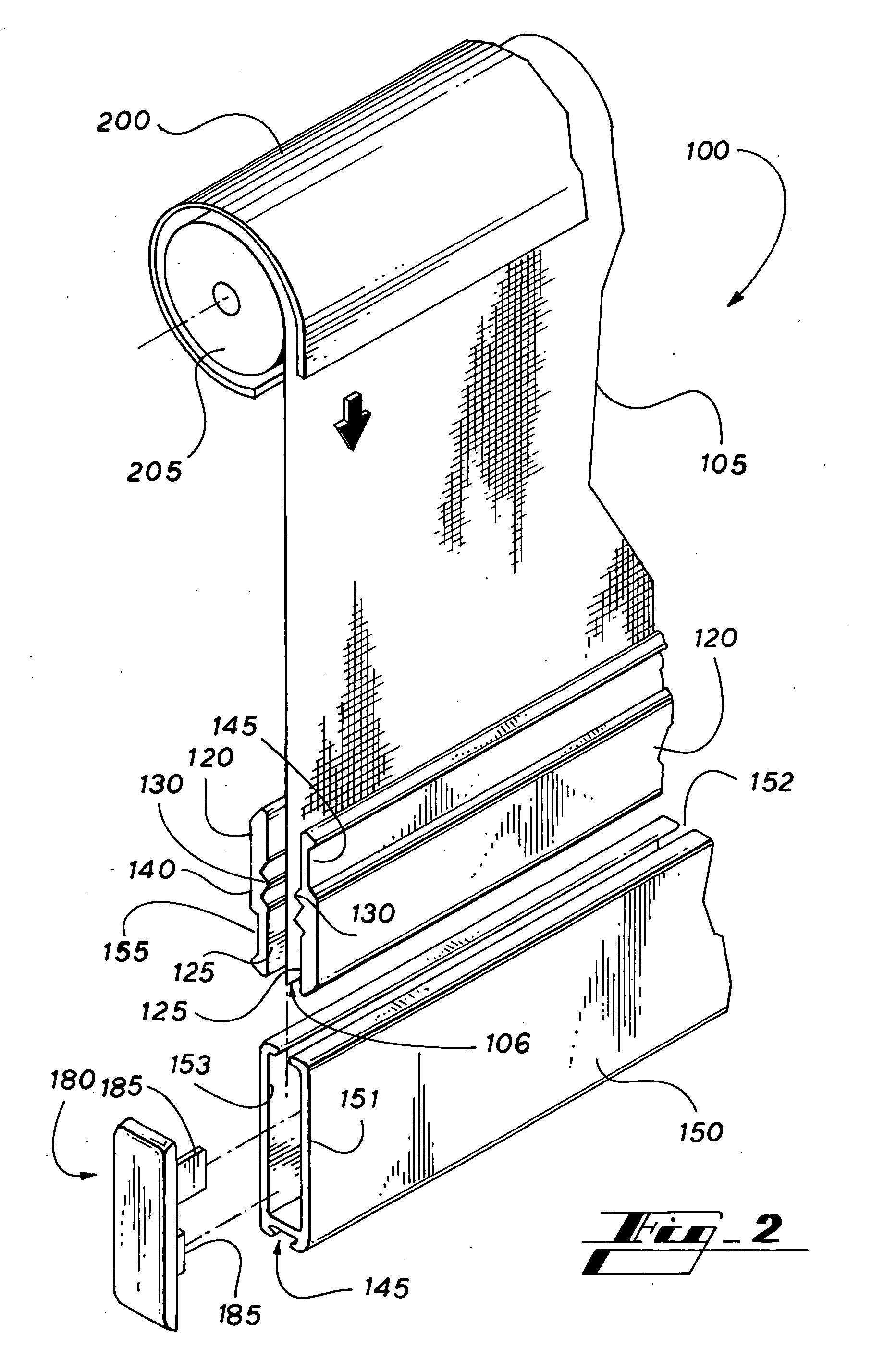
[0047] Referring to the drawings wherein like reference numerals designate corresponding parts throughout the several figures, reference is made first to FIG. 2 that illustrates a perspective exploded view of the constituent components of an embodiment of a pull bar screen apparatus 100. In general, the apparatus 100 includes a sheet of screen 105 material that can be formed from a variety of materials, but typically is formed of a suitable mesh material such as vinyl. The apparatus 100 further includes two opposing lock bars 120 that are typically inverted mirror images of one another. The lock bars 120 typically include an inner corrugated surface 125, the corrugated inner surface being generally formed from elongated parallel ridges 130. The corresponding elongated ridges 130 of the inverted mirror image lock bar 120 are placed together in mated engagement when the opposing lock bars 120 are placed together with the inner corrugated surfaces 125 in mechanical contact. A lower edg...


PUM


Abstract

A pull bar screen apparatus and system in which screen is mechanically attached directly to a pull bar. Weld-less friction-lock cold-joining of screen and pull bar provides an improved pull-bar screen apparatus used in retractable pull screens. The pull bar screen apparatus and system remove the need for attaching a vinyl strip to the screen. Instead, the screen is flattened to retain its form and structural integrity. On one elongated end of the screen, an upper and lower lock bar are placed on either side of the screen. Corrugated ridges in the lock bars pinch the screen and hold it in place. A lock bar casing is placed under pressure around the upper and lower lock bars which hold the lock bars in position and thereby retain the screen.

Description

BACKGROUND [0001] I. Field of the Invention [0002] The present invention relates generally to the field pull bar screens and more particularly to a pull bar screen apparatus and system. [0003] II. Description of the Related Art [0004] Fixed frame screens have been used for seasonal placement typically to prevent insects from entering into houses while having windows open. Fixed frame screens are either left in place permanently or are taken out in the off-season for storage in attics, basements and the like. The fixed frame screens typically represent perpetual maintenance problems because they are frail. In contrast, retractable screen systems are housed in a cassette that is permanently mounted to a portion of either a door or window frame and never need to be removed for storage. When not in use, they simply retract into the permanently mounted cassette. Retractable screens have also increased in popularity for use as sun screens. [0005] In manufacturing retractable screens, ther...

Claims


Application Information

Patent Timeline
Patent Type & Authority Applications(United States)
IPC IPC(8): E06B9/08
CPCE06B9/54
Inventor HORVATH, LOUIS
Owner HORVATH LOUIS
Why Eureka
Try Eureka