Fluid product dispenser

a technology of product dispensers and dispensers, which is applied in the field of dispensers, can solve the problems of relative difficulty and high manufacturing cost, and cannot be optimally compatible with the liquid product being used, and achieve the effect of reducing the volume of the attendant air chamber

Inactive Publication Date: 2007-08-23
TECHN CONCEPTS BENTFIELD
View PDF18 Cites 23 Cited by
  • Summary
  • Abstract
  • Description
  • Claims
  • Application Information

AI Technical Summary

Benefits of technology

[0017] A liquid inlet device that incorporates teachings of the present invention may be relatively easy to manufacture (e.g., have relatively high manufacturing tolerances, etc.) and be more compatible than existing liquid inlet devices with the liquid product to be dispensed. A liquid inlet device according to the present invention may include a body of solid material in which at least one constrictive passage is provided, the constrictive passage being constantly open and serving to allow passage of liquid product back and forth between the liquid reservoir and the liquid chamber.
[0023] If desired, the effects of such back migration on the (quantity and / or quality of the) dispensed fluid product may be mitigated by, for example: appropriately enlarging the volume of the liquid chamber; and, in the case of a foam pump, appropriately reducing the volume of the attendant air chamber.

Problems solved by technology

Since they generally comprise precision moving parts, they may be relatively difficult and expensive to manufacture.
Moreover, machining or performance specifications for these parts often require them to be made from specific materials, which may not be optimally compatible with the liquid product being used (e.g., a metal ball bearing may corrode as a result of contact with certain components of liquid soap).

Method used


Image

  • Fluid product dispenser
  • Fluid product dispenser
  • Fluid product dispenser

Examples


Embodiment Construction

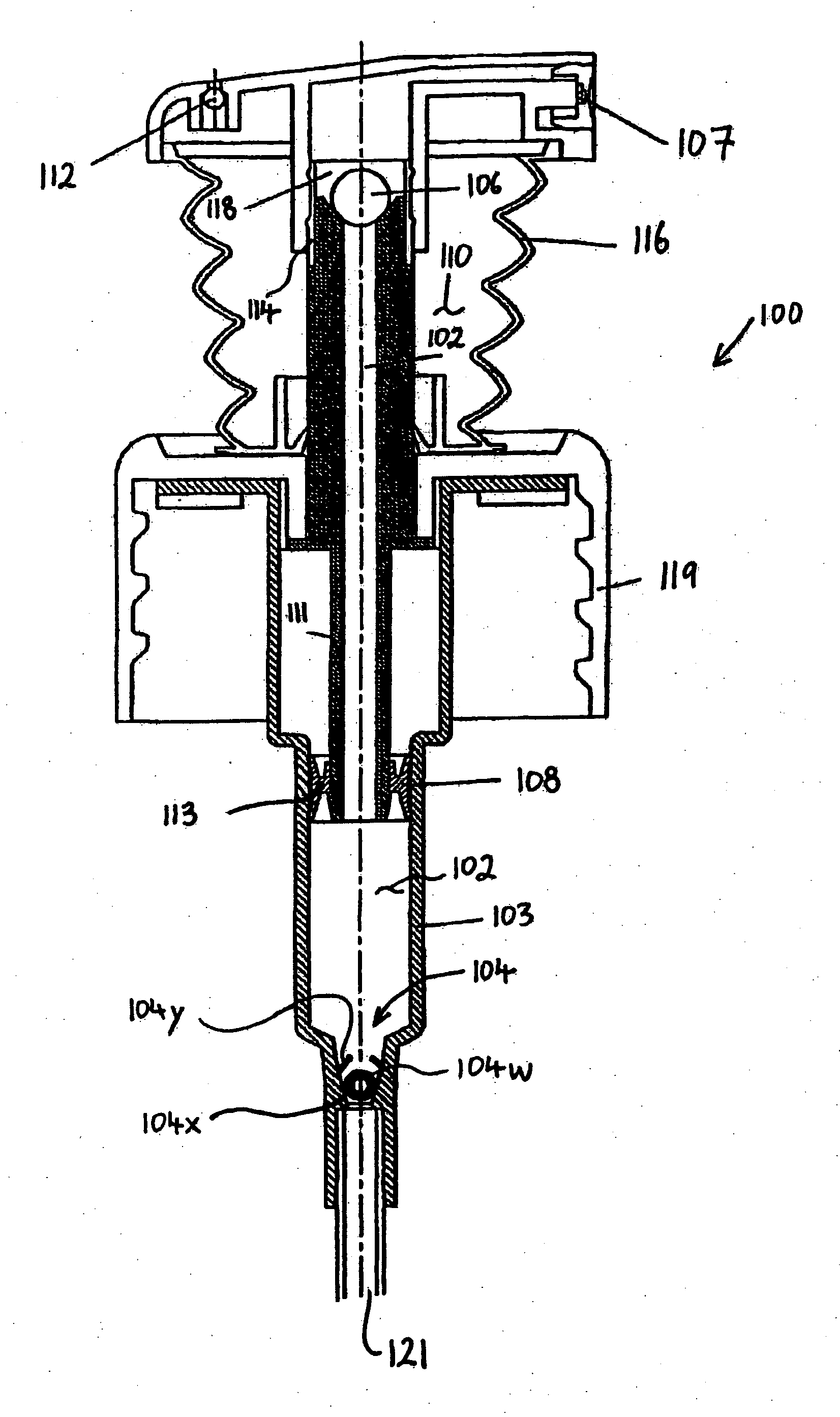
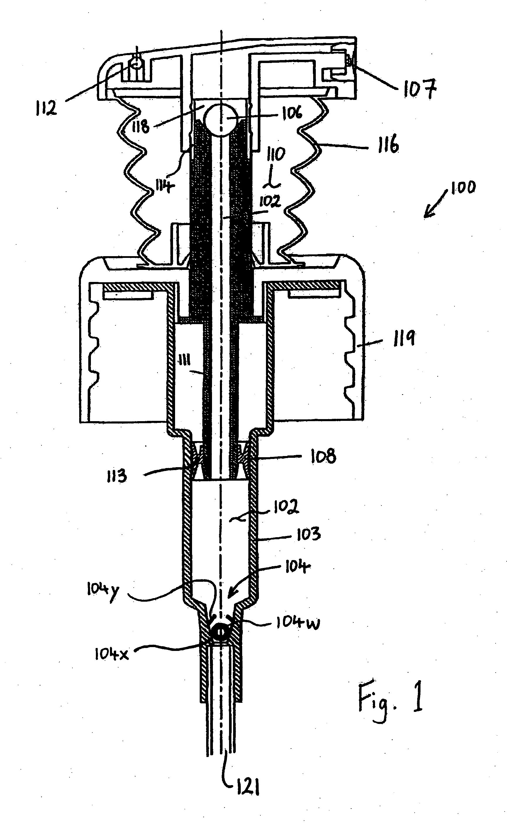
[0048]FIG. 1 renders a longitudinal cross-sectional view of part of a dispenser for dispensing a fluid product. More specifically, FIG. 1 depicts a pump 100 that may be employed in such a dispenser. In use, the pump 100 may be connected to a liquid reservoir for storing a liquid product; such a liquid reservoir is not depicted in FIG. 1, but will be discussed later. In this particular case, the fluid product concerned is a foam, produced by mixing a liquid product with air.

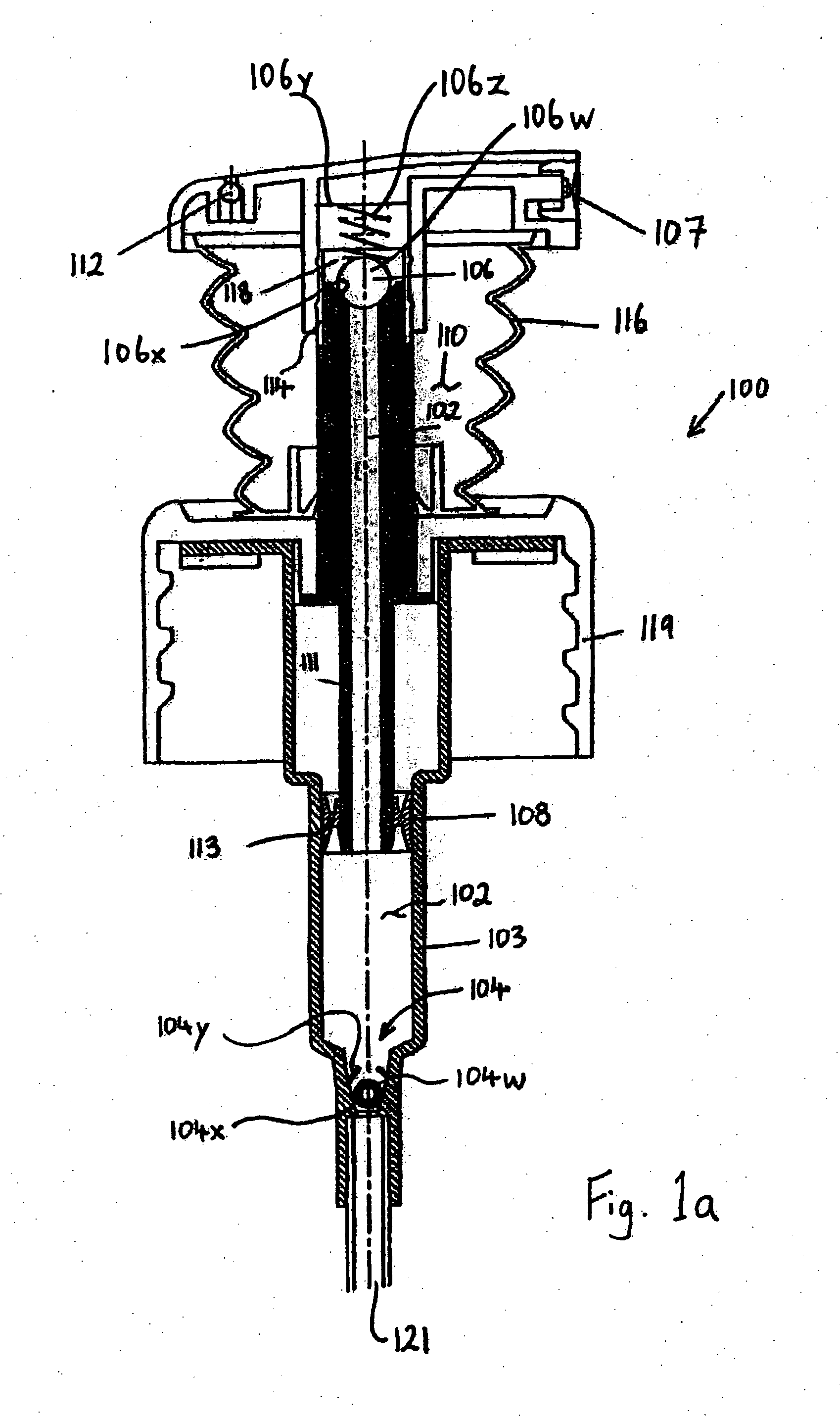
[0049] The pump 100 includes a liquid chamber 102 for containing a dose of the liquid product, a liquid outlet valve 106 for regulating passage of liquid product from the liquid chamber 102 to a dispensing head 107, and compression means 108 for applying a compressional force to liquid product in the liquid chamber 102, thus forcing liquid product from the liquid chamber 102 through the liquid outlet valve 106 and through the dispensing head 107. The pump 100 may also include an air chamber 110 for containing air...


PUM


Abstract

A dispenser for dispensing a fluid product includes a liquid reservoir for storing a liquid product and a pump that is connected to the liquid reservoir. The pump may include a liquid chamber for containing a dose of the liquid product, a liquid outlet valve for regulating passage of liquid product from the liquid chamber to a dispensing head, compression means for applying a compressional force to liquid product in the liquid chamber, thus forcing liquid product from the liquid chamber through the liquid outlet valve and through the dispensing head. The dispenser may also include a liquid inlet device for administering admission of liquid product into the liquid chamber from the liquid reservoir. The liquid inlet device may include a body of solid material in which at least one constrictive passage is provided. The constrictive passage may be constantly open and serve to allow passage of liquid product back and forth between the liquid reservoir and the liquid chamber.

Description

CROSS-REFERENCE TO RELATED APPLICATIONS [0001] This application claims priority pursuant to the Paris Convention to European Patent Application 06075177.3, filed Jan. 25, 2006, the disclosure of which is hereby incorporated herein, in its entirety, by this reference. This application also claims the benefit of U.S. Provisional Application No. 60 / 762,523, filed Jan. 27, 2006, the disclosure of which is hereby incorporated herein, in its entirety, by this reference.BACKGROUND OF THE INVENTION [0002] 1. Field of the Invention [0003] The present invention relates to dispensers for dispensing fluid products. More specifically, the present invention relates to a dispenser that includes a liquid reservoir for storing a liquid product and a pump that is connected to the liquid reservoir and that includes, among other things, a liquid inlet valve with a constricted, or relatively small, passageway. [0004] 2. Background of Related Art [0005] Dispensers are well known, and are described, inter...

Claims


Application Information

Patent Timeline
Patent Type & Authority Applications(United States)
IPC IPC(8): B67D5/58B67D7/76
CPCA47K5/1205A47K5/1207B05B11/3094B05B11/3066B05B11/3087B05B7/0025B05B11/1066B05B11/1087B05B11/1094
Inventor GANZEBOOM, WILHELMUS E.KADIKS, FEDOR C.
Owner TECHN CONCEPTS BENTFIELD
Why Eureka
Try Eureka