Reusable isolation joint form

a concrete form and isolation joint technology, applied in the direction of forms/shuttering/falseworks, shaping building parts, constructions, etc., can solve the problems of sand being removed from inside the form, destroying the cavity of the wooden form, waste in the time it takes to construct, set and fill the form, waste in the time it takes to remove and destroy the form, etc., to achieve the effect of eliminating waste and facilitating the construction of the form

Inactive Publication Date: 2007-08-23
BLACKMON RONALD
View PDF15 Cites 20 Cited by
  • Summary
  • Abstract
  • Description
  • Claims
  • Application Information

AI Technical Summary

Benefits of technology

[0008] It is an object of the re-usable isolation joint to provide a form that is used to make an isolation joint and then removed from the floor and used in future locations, this provides the benefits of easier construction of the forms as well as elimination of the waste that is present when wooden forms are constructed and then destructively removed from the floor slab.

Problems solved by technology

After the concrete is hardened the concrete is removed from the top of the form, the sand is removed from inside the form and the wooden form is destructively removed from the cavity.
There is waste in both the time it takes to construct, set and fill the form as well as the time it takes to remove and destroy the form to clear it from the cavity.
Leaving the form in the floor of the building is not acceptable for building code in some areas.
Since the form remains in the floor the form is also not re-usable.
Leaving the form in the floor of the building is not acceptable for building code in some areas.
Since the form remains in the floor the form is also not re-usable.
Leaving the form in the floor of the building is not acceptable for building code in some areas.
Since the form remains in the floor the form is also not re-usable.
Leaving the form in the floor of the building is not acceptable for building code in some areas.
Since the form remains in the floor the form is also not re-usable.

Method used


Image

  • Reusable isolation joint form
  • Reusable isolation joint form
  • Reusable isolation joint form

Examples


Embodiment Construction

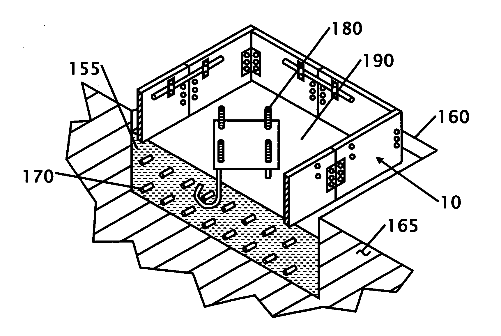
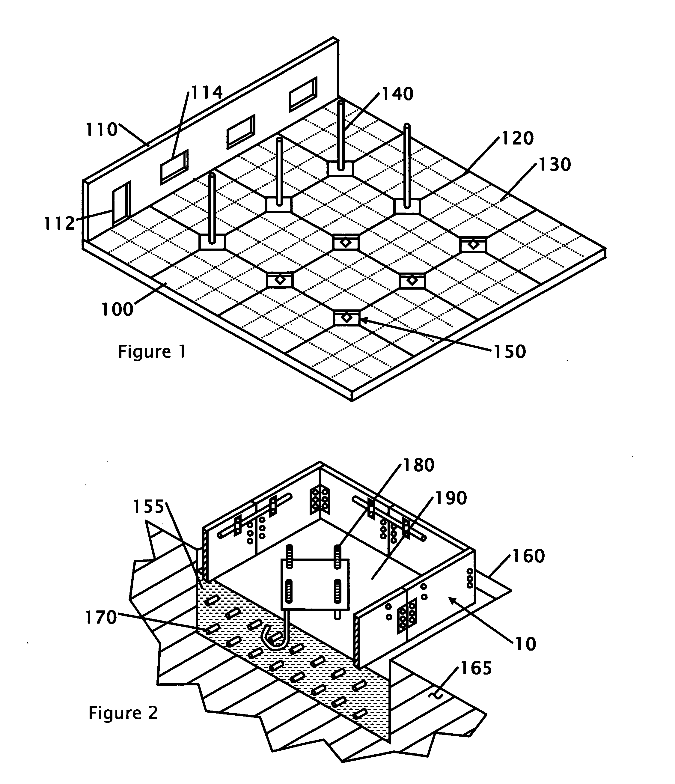
[0023] Referring to FIG. 1 that shows an isometric view of a building construction site showing where the isolation form is used. This figure shows a typical floor 100 with a wall section 110 installed on one side of the floor. Columns 140 are shown inside of the diamond isolation joint pocket 150. The columns 140 support the roof structure or any upper floor sections (not shown). Because of the weight that exists in the roof or upper floors a footing must be poured under the columns to support the weight. The description of the footing and the use of the form for the diamond isolation joint are described in more detail with FIGS. 2-5. Typically the footings that exist under the floor 100 are excavated and poured prior to pouring the floor slab. Due to the separate footing pour under the floor as well as the need for expansion and movement, the concrete at the support columns is poured separately from the footing and the floor, so it can move semi-independently from the floor. The e...


PUM

PropertyMeasurementUnit
heightaaaaaaaaaa
heightaaaaaaaaaa
depthaaaaaaaaaa

Abstract

A re-usable form for making diamond isolation joints used in the construction of buildings is disclosed. The form is made from wood, plastic cardboard, plastic sheet, wax coated cardboard or other material that can easily be separated from concrete. The form is placed onto a footing for a column or block out and the floor is poured around the form. After the floor is cured the form is collapsed inside itself to create the void of the diamond isolation joint. The form can be re-used in another isolation joint in the same building or on future construction projects. The form can be fabricated on site in various heights and dimensions. The form is folded or collapsed to make it easier to transport and store.

Description

FIELD OF THE INVENTION [0001] This invention relates to a concrete form for making isolation joints in building construction. More particularly, the concrete form is fabricated to allow it to be easily assembled into place, the concrete is poured around the form and the form is removed and available for use in another location. The form is collapsible allowing it to fold upon itself allowing for easier transportation and storage. BACKGROUND OF THE INVENTION [0002] The construction or forming of diamond isolation joints today is most commonly performed by constructing a wooden form over the footing of a support column or block out. The form is then filled with sand and the floor is poured around and on top of the form. After the concrete is hardened the concrete is removed from the top of the form, the sand is removed from inside the form and the wooden form is destructively removed from the cavity. Because the form is fabricated from solid pieces of wood it must be discarded when re...

Claims


Application Information

Patent Timeline
Patent Type & Authority Applications(United States)
IPC IPC(8): B28B7/28
CPCE04G15/063E04G13/00
Inventor BLACKMON, RONALD
Owner BLACKMON RONALD
Why Eureka
Try Eureka