Backlight module and liquid crystal display

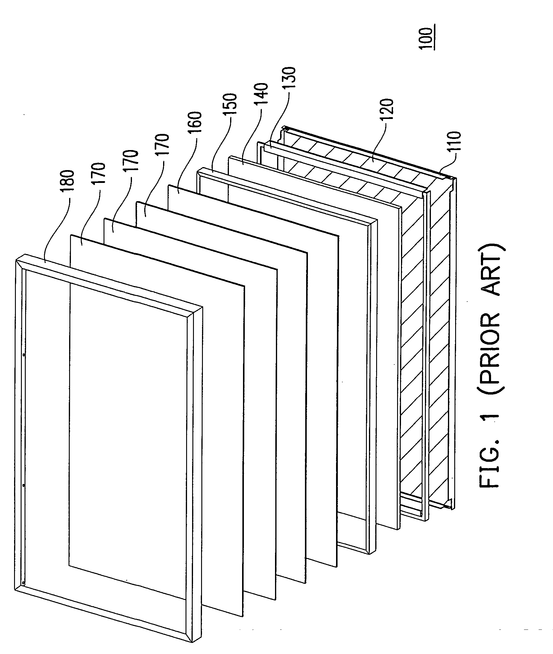
a backlight module and liquid crystal display technology, applied in lighting and heating apparatus, lighting device details, instruments, etc., can solve the problems of affecting the assembling efficiency of the backlight module b>100/b>, damage to the optical film, and the bulky nature of traditional cathode ray tube displays, etc., to achieve the effect of improving the assembling and maintenance efficiency of the backlight modul

Inactive Publication Date: 2007-08-23
CHUNGHWA PICTURE TUBES LTD
View PDF6 Cites 1 Cited by
  • Summary
  • Abstract
  • Description
  • Claims
  • Application Information

AI Technical Summary

Benefits of technology

[0010] Accordingly, one objective of the present invention is to provide a backlight module for preventing the optical films from being damaged and decreasing the possibilities of external particles entering into the optical films, and therefore improve the assembling efficiency and the maintenance efficiency of the backlight module.
[0011] Another objective of the present invention is to provide a liquid crystal display having the above backlight module, which has higher assembling efficiency and superior maintenance efficiency.
[0022] The present invention employs independent light source module and optical film module, so that the light source module and the optical film module are detachably joined. Therefore, either the light source module or the optical film module is broken, only the broken one needs to be disassembled. Because not all components of the backlight module have to be disassembled in sequence during repairing the possibilities of the optical films being damaged and external particles entering into the optical films are reduced. Since the light source module or the optical film module is independently assembled or repaired, the assembling and maintenance efficiency of the backlight module is improved.

Problems solved by technology

Traditional cathode ray tube (CRT) displays are quite bulky owing to the electron chamber structure and may be harmful due to the radiation.
Therefore, the assembling efficiency of the backlight module 100 is adversely affected.
Therefore, disassembling the backlight module 100 is time-consuming and may easily cause damages to the optical films 170.

Method used


Image

  • Backlight module and liquid crystal display
  • Backlight module and liquid crystal display
  • Backlight module and liquid crystal display

Examples


Embodiment Construction

[0029] Reference will now be made in detail to the present preferred embodiments of the invention, examples of which are illustrated in the accompanying drawings. Wherever possible, the same reference numbers are used in the drawings and the descriptions to refer to the same or like parts.

[0030] The backlight module comprises an independent light source module and an independent optical film module. The light source module and the optical film module are independently assembled and / or repaired, such that the assembling efficiency and the maintenance efficiency of the backlight module are increased. Thereinafter, embodiments are recited to describe the backlight module of the present invention in further details.

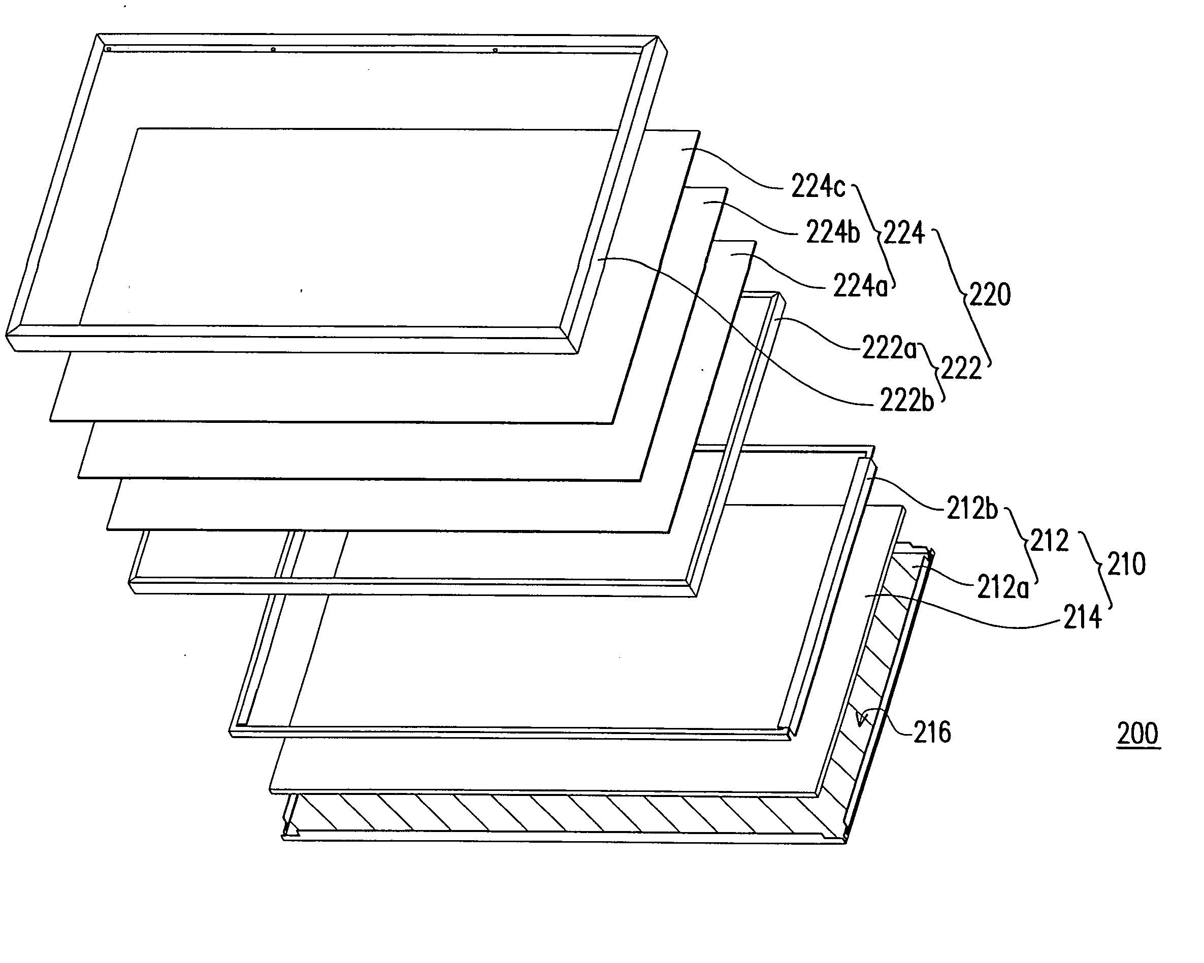
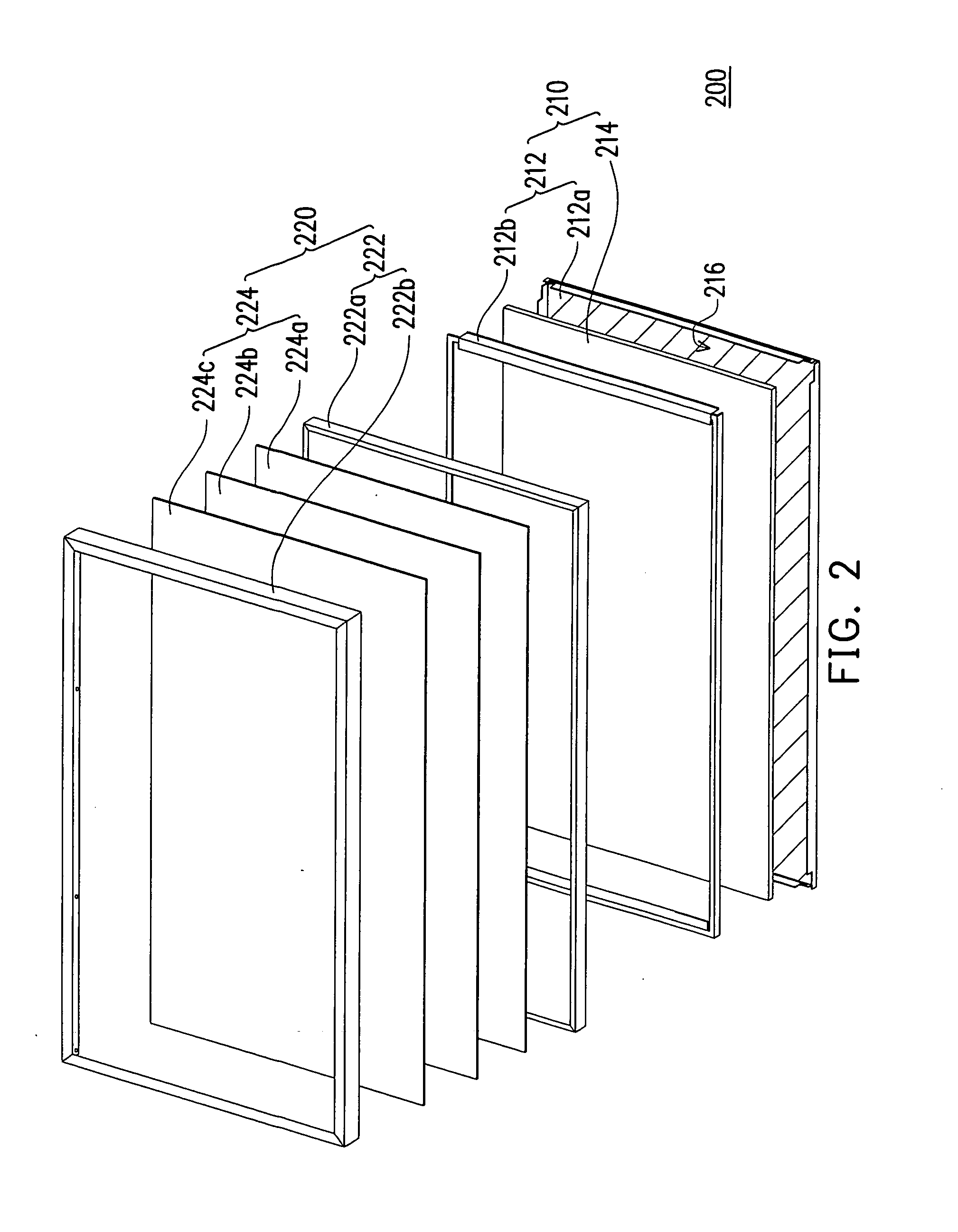
[0031]FIG. 2 is an exploded view of a backlight module according to a preferred embodiment of the present invention. In FIG. 2, the backlight module 200 comprises a light source module 210 and an optical film module 220. The light source module 210 includes a first frame mo...


PUM


Abstract

A backlight module having a light source module and an optical film module is provided. The light source module includes a first frame module and a light source. The light source is disposed in the first frame module. The optical film module includes a second frame module and a plurality of optical films. The optical films are disposed in the second frame module. The optical film module is detachably disposed on the light source module.

Description

BACKGROUND OF THE INVENTION [0001] 1. Field of the Invention [0002] The present invention generally relates to a backlight module and a display device, in particular, to a backlight module with increased assembling efficiency and a liquid crystal display having the backlight module. [0003] 2. Description of Related Art [0004] The size of visual or image devices becomes smaller in order to adapt to the modern life. Traditional cathode ray tube (CRT) displays are quite bulky owing to the electron chamber structure and may be harmful due to the radiation. Following the developments in optoelectronic technology and the semiconductor fabrication technology, flat panel displays, including liquid crystal display (LCD), organic electroluminescence diode display (OLED) and flat panel display (FPD), have became the key display products in the market. [0005] According to the types of the light source, there are three types of LCD, including reflective LCD, transmissive LCD and transflective LC...

Claims


Application Information

Patent Timeline
Patent Type & Authority Applications(United States)
IPC IPC(8): F21V7/04
CPCG02F1/133606
Inventor LIN, WEI-CHICHU, KUO-LIANGWANG, YUN-SHIH
Owner CHUNGHWA PICTURE TUBES LTD
Why Eureka
Try Eureka