Clamping mechanism

Active Publication Date: 2007-08-23
OSWALD FRED
View PDF9 Cites 5 Cited by
  • Summary
  • Abstract
  • Description
  • Claims
  • Application Information

AI Technical Summary

Benefits of technology

[0008]It has therefore been found desirable to mount a vibrator laterally on the side of a reinforcing bar or on such a bar incorporated in a grid. A quick engagemen

Problems solved by technology

But these vibrators have certain problems.
If a reinforcing bar is too tall—for example, it projects a distance above scaffolding—it is too high for the vibrator operato

Method used


Image

  • Clamping mechanism
  • Clamping mechanism
  • Clamping mechanism

Examples


Example

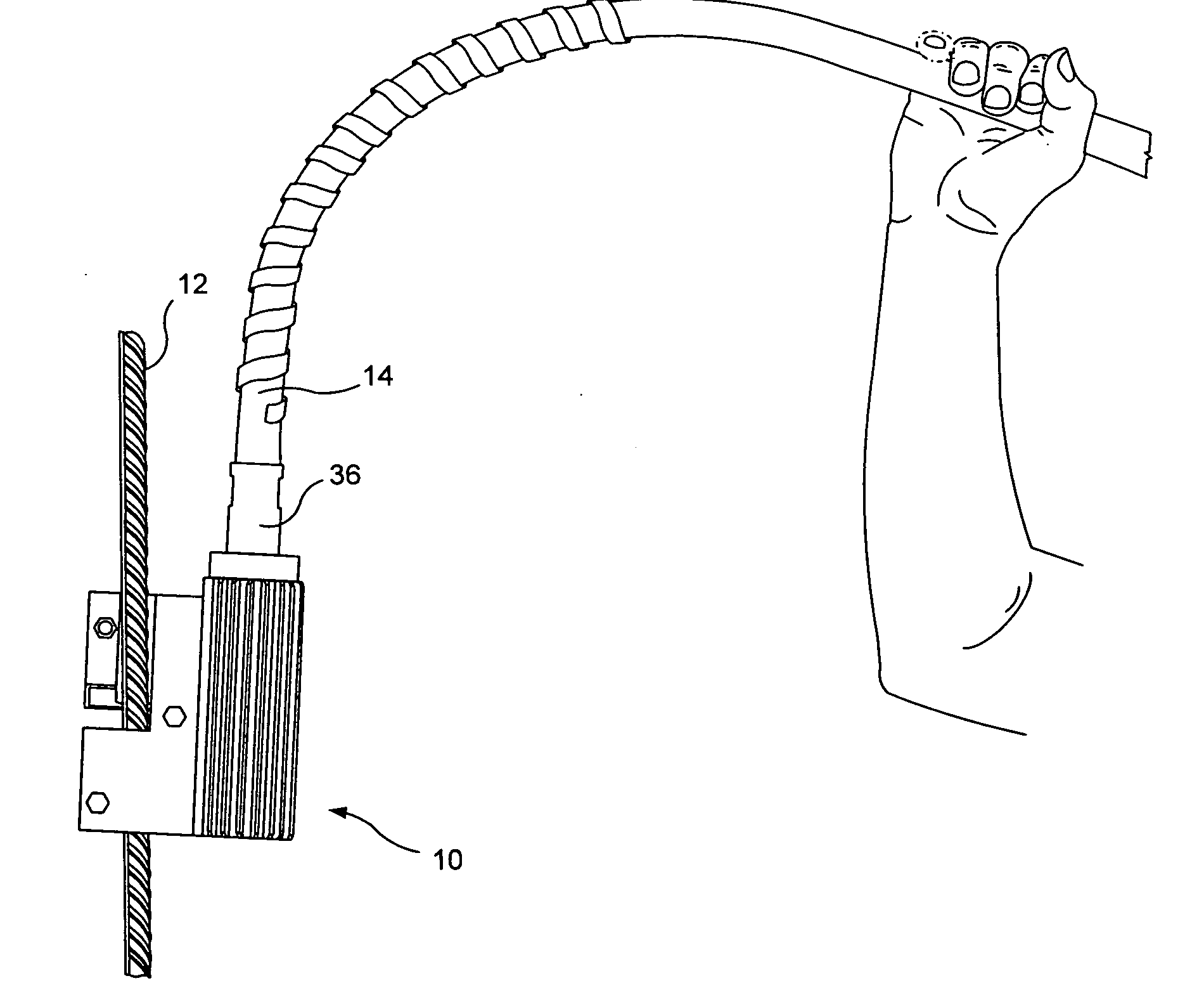
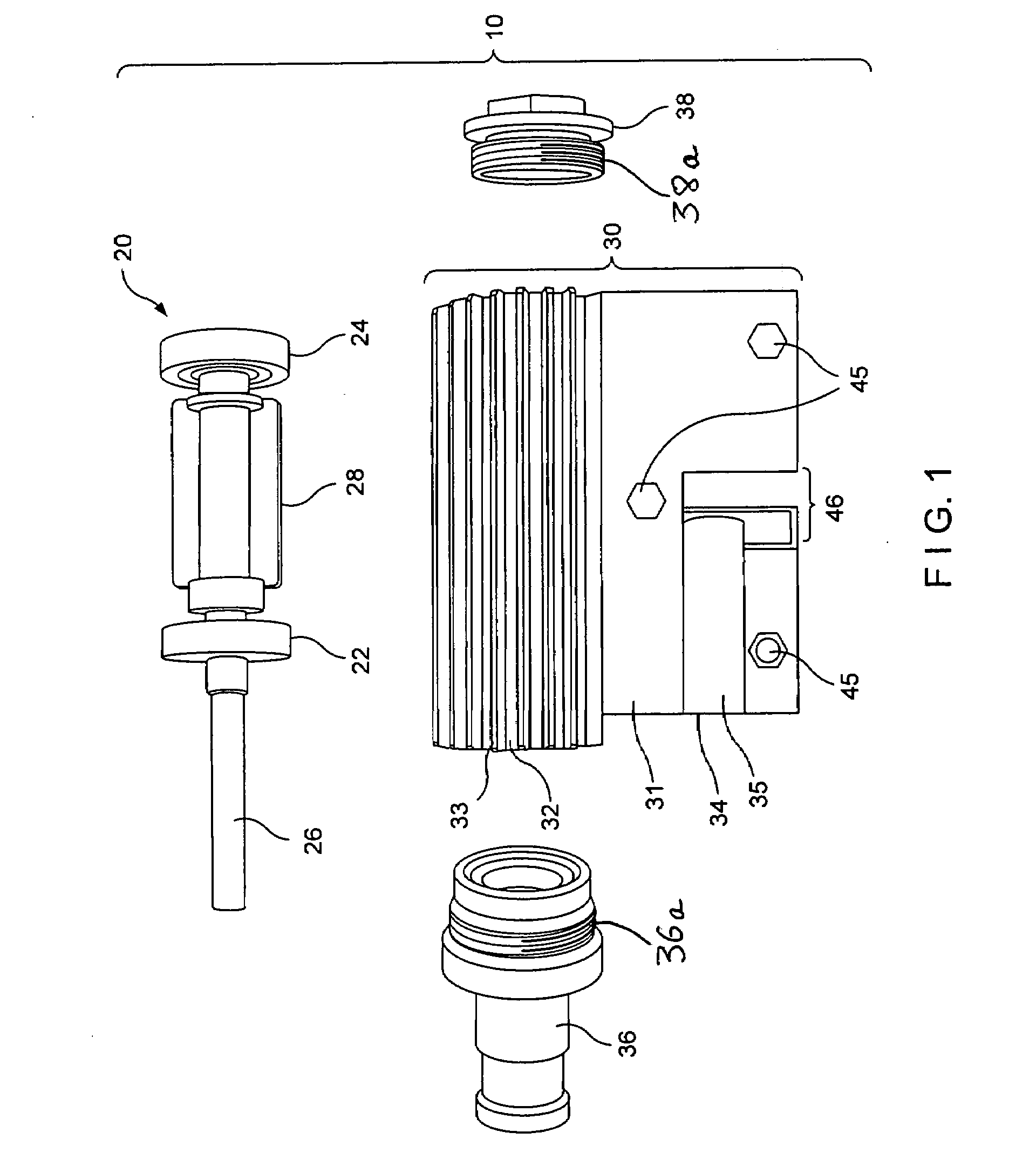
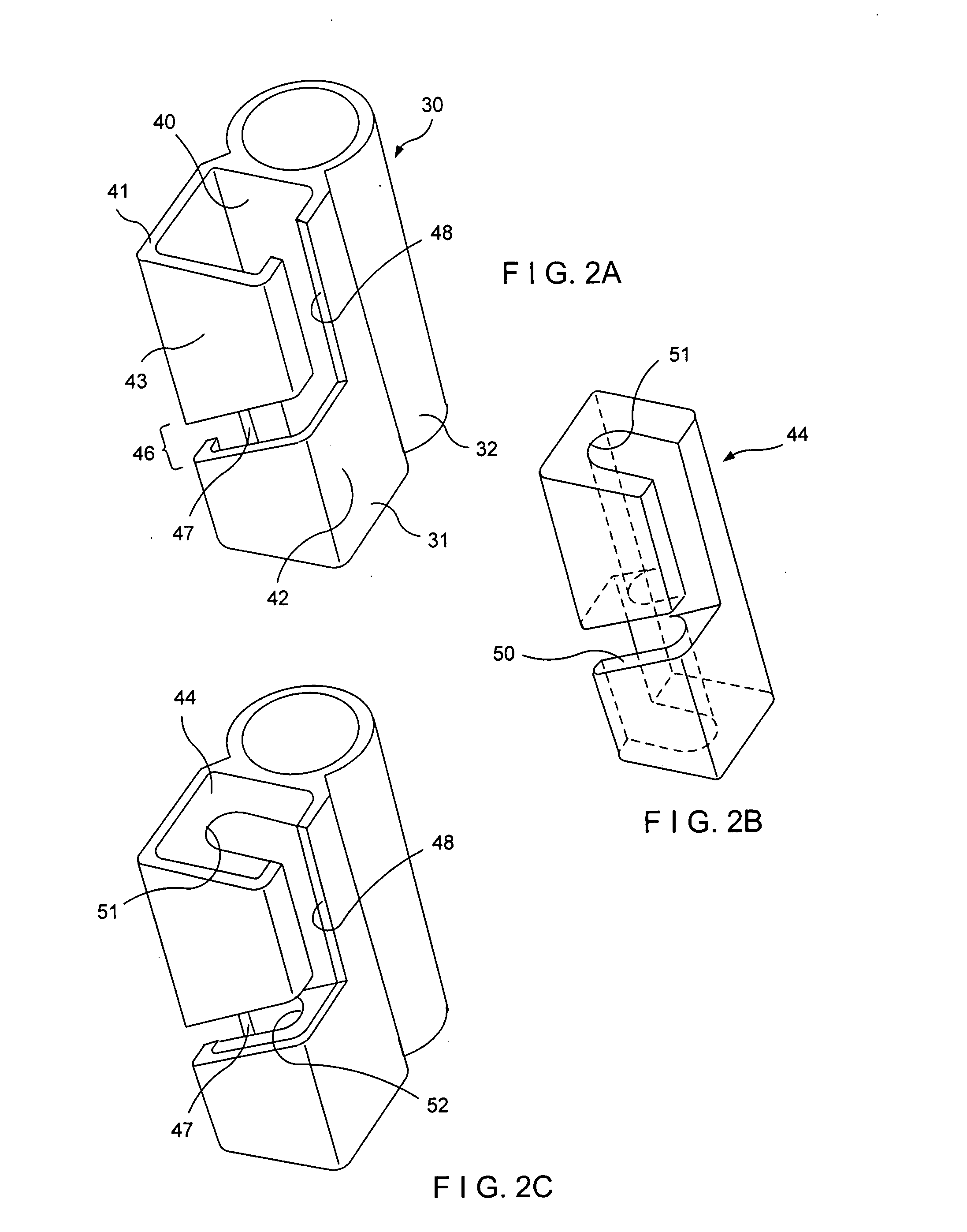
[0022]Referring now to the drawings, and specifically to FIG. 1, a vibrator 10 includes a housing 30 including a cylindrical vibration portion 32 and a clamping portion 31. In the preferred embodiment, most clearly shown in FIGS. 2A and 2C of the drawings, the cylindrical vibration portion 32 and the clamping portion 31 are two parts of an integral casing. However, the cylindrical portion 32 and the clamping portion 31 could be separate components secured to each other. Such separate components could be secured to each other by, for example, mating keyways, bolts, rivets, or like fasteners. However, in operation, the vibrator vibrates on the order of 10,000 vibrations per minute and separate components could, in some circumstances, create problems. Thus, in the preferred embodiment the cylindrical portion and the clamping portion are an integral unit, and the unit could be an integral casting of, for example, aluminum or the two component portions could be permanently welded togethe...


PUM

PropertyMeasurementUnit
Angleaaaaaaaaaa
Angleaaaaaaaaaa
Weightaaaaaaaaaa

Abstract

A clamping mechanism particularly for clamping a vibrator to a reinforcing bar. The clamping mechanism provides a slot which intersects a channel. The channel is longitudinally open in one direction at one side of said intersecting slot and longitudinally open in the opposite direction at the other side of said intersecting slot. A reinforcing bar or other member to be engaged first enters the slot then moves into the channel. Once in the channel, the bar or other member is positively retained therein.

Description

[0001]This application claims the benefit of U.S. Provisional Application No. 60 / 774,400, filed Feb. 17, 2006, and incorporates same by reference.BACKGROUND OF THE INVENTION[0002]The invention relates to a clamping mechanism and is particularly concerned with the clamping of a vibrator to a reinforcing bar.[0003]In the construction industry, it is frequently necessary to lay a large area of concrete. Such areas can include, for example, foundations for buildings, floors, driveways, columns, walls, ramps, etc.[0004]Concrete is a mixture of cement, sand, and stones, Lime is an ingredient in cement, and water is mixed with the components of the mixture to activate the lime and form a mix or slurry. Concrete exhibits characteristics of strength in compression but is relatively weak in tension.[0005]To increase strength in tension, it is common practice to prepare a grid of reinforcing bars (“rebars”) and then to pour concrete over and around the grid, so that the reinforcing bars improv...

Claims


Application Information

Patent Timeline
IPC IPC(8): E04G21/08B01F11/00
CPCE04G21/068B28B1/0935
Inventor OSWALD, FRED
Owner OSWALD FRED
Why Eureka
Try Eureka