Multistep Index Optical Fiber

Inactive Publication Date: 2007-08-23
FUJIFILM CORP +1
View PDF3 Cites 0 Cited by
  • Summary
  • Abstract
  • Description
  • Claims
  • Application Information

AI Technical Summary

Benefits of technology

[0016] For the purposes of comparison, FIG. 2A is a graph that illustrates an example of the basic refractive index distribution properties of a conventional five step multi step index optical fiber. FIG. 2B is a schematic diagram of the cross section of the conventional five step multi step index optical fiber. In the conve

Problems solved by technology

However, the maximum bandwidth obtainable with conventional multi step index optical fibers is about 1 GHz / 100 m. It is considered to be difficult to obtain bandwidths on the order of several GHz / 100 m with conventional multi step index optical fibers.

Method used


Image

  • Multistep Index Optical Fiber
  • Multistep Index Optical Fiber
  • Multistep Index Optical Fiber

Examples


Embodiment Construction

[0024] Hereinafter, embodiments of the present invention will be described in detail with reference to the drawings.

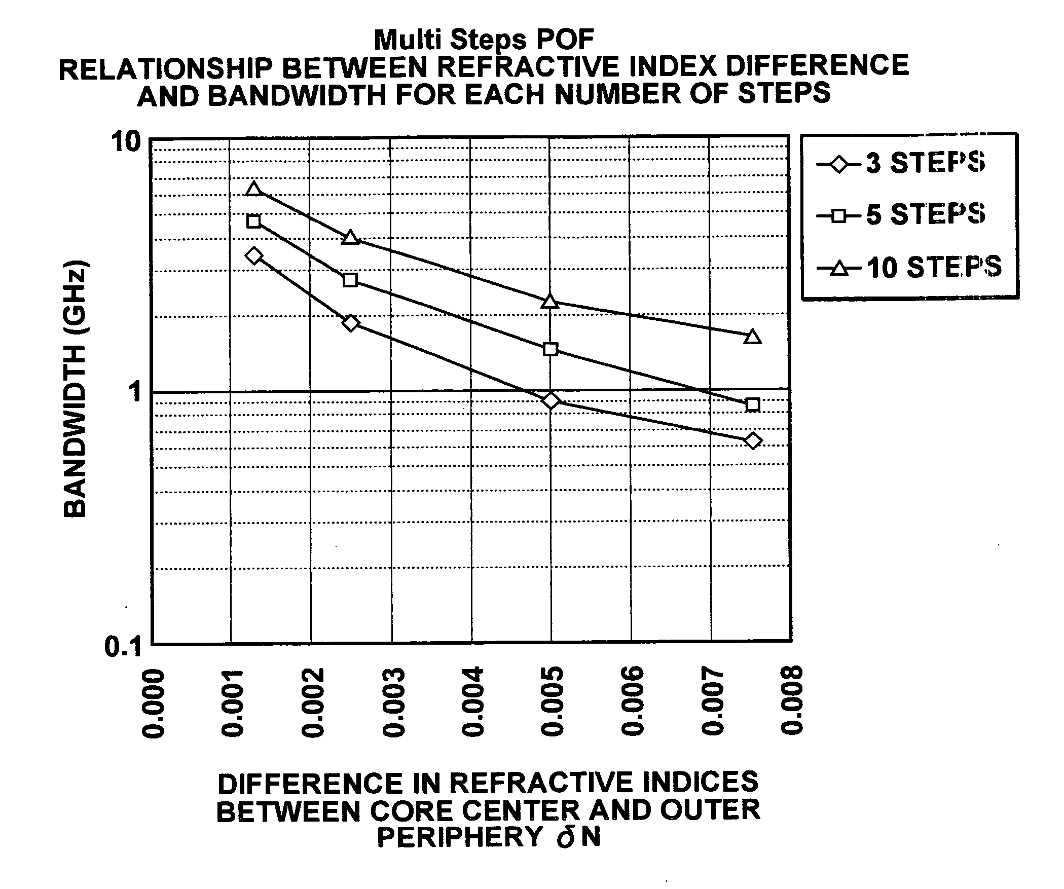
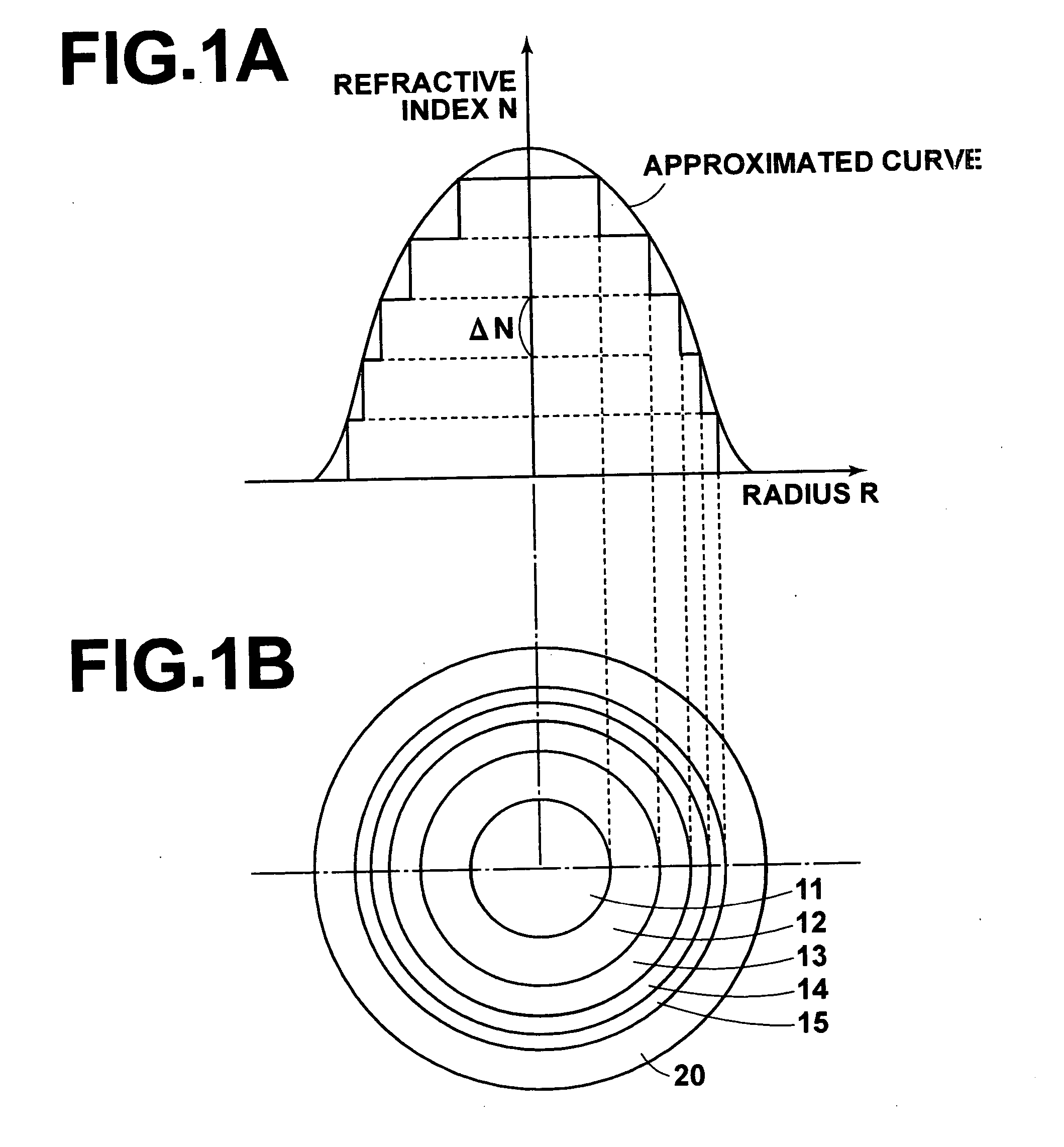
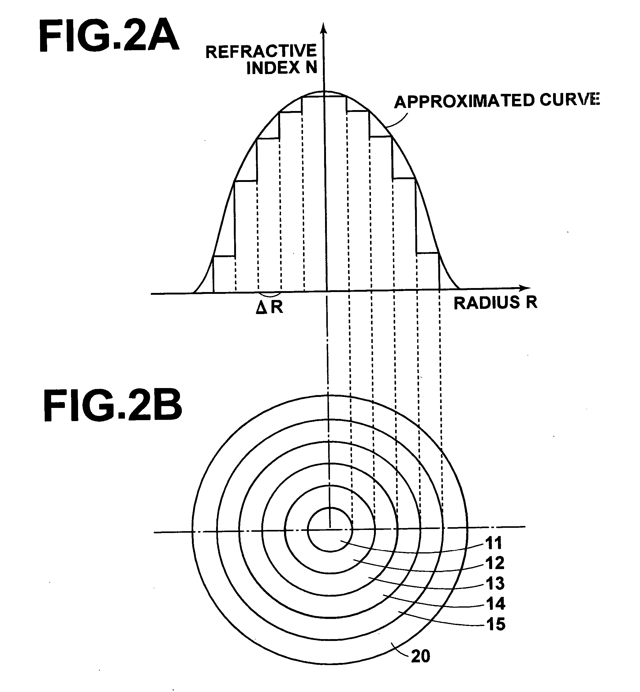
[0025] First, the results of simulations for deriving bandwidths regarding a multi step index fiber having the basic structure illustrated in FIG. 1B obtained by a computer will be described. The multi step index optical fiber illustrated in FIG. 1B had five steps in core refractive indices. In addition to this case, simulations were performed for configurations in which there are three and ten steps in core refractive indices. In all three cases, the numerical aperture (N.A.) of an incident optical system was set to 0.3, the intensity distribution of incident light was assumed to be a Gaussian distribution, and the length of the optical fiber was set to 100 m.

[0026] The simulation results for configurations in which there are three, five, and ten steps in core refractive indices are illustrated in FIGS. 3, 4, and 5, respectively. The bandwidth was derived for each c...


PUM


Abstract

A multi step index optical fiber includes at least two concentrically arranged core portions, each having constant refractive index. The refractive indices of the core portions decrease toward the outer periphery of the optical fiber. The refractive indices of the core portions are set such that differences ΔN between refractive indices of adjacent core portions are uniform, and the distribution of the refractive indices approximates a G power distribution. Thereby, bandwidths on the order of several GHz / 100 m can be realized.

Description

TECHNICAL FIELD [0001] The present invention relates to an optical fiber. More specifically, the present invention relates to a multi step index optical fiber, comprising a plurality of core portions having different refractive indices from each other. BACKGROUND ART [0002] There are known conventional multi step index optical fibers, as disclosed in Japanese Unexamined Patent Publication No. 10 (1998) -111414. Multi step index optical fibers comprise at least two concentrically arranged core portions, each having a constant refractive index. The refractive indices of the core portions decrease from a central core portion to core portions at the outer periphery of the optical fiber. [0003] The refractive indices of the plurality of core portions of these multi step index optical fibers are generally set such that they change along a so called G power distribution. In the G power distribution, the refractive index N at a position at radius R from the core center can be approximated b...

Claims


Application Information

Patent Timeline
IPC IPC(8): G02B6/036G02B6/028
CPCG02B6/02038G02B6/03688G02B6/0288G02B6/0281
Inventor IWASAKI, OSAMU
Owner FUJIFILM CORP
Why Eureka
Try Eureka