Soft magnetic film and thin film magnetic head using the same

a thin film and magnetic head technology, applied in the field of soft magnetic film and thin film magnetic head using the same, can solve the problems of reducing the bs described above, unable to form dense crystals, etc., and achieve the reduction of current loss in a high frequency region, high saturated magnetic flux density bs, and high resistivity

Active Publication Date: 2006-05-30
TDK CORPARATION
View PDF13 Cites 0 Cited by
  • Summary
  • Abstract
  • Description
  • Claims
  • Application Information

AI Technical Summary

Benefits of technology

[0020]Accordingly, the present invention was made to solve the problem described above, and an object of the present invention is to provide a soft magnetic film composed of an FeNiMo alloy and a thin film magnetic head using the same, in which, even when the Fe content is high as compared to that in the past, the FeNiMo alloy stably shows a high saturated magnetic flux density Bs together with a high resistivity.
[0023]In the present invention, the soft magnetic film described above is formed by plating. By plating, the thickness of the soft magnetic film can be relatively freely changed, and when frame plating is used, the soft magnetic film described above can be formed so as to have a large thickness and an optional shape. In addition, the soft magnetic film formed by plating tends to have a uniform thickness as compared to that of a soft magnetic film obtained by vacuum deposition such as sputtering. When the thickness of the soft magnetic film is increased, the difference in uniformity of film thickness between the soft magnetic film formed by plating and that formed by vacuum deposition such as sputtering is increased.
[0026]In addition, in the soft magnetic film of the present invention, since Mo is contained at the composition ratio described above, the resistivity is increased.
[0033]The soft magnetic film according to the present invention is composed of an FeNiMo alloy in which the mass percent ratio of Fe to Ni is 0.65 or more, and more preferably 0.70 or more. Although having a high Fe content as described above, the soft magnetic film of the present invention described above can stably show a high saturated magnetic flux density Bs, such as 1.50 (T) or more, 1.67 (T) or more, 1.78 (T) or more, or 1.90 (T) or more. The soft magnetic film described above is the present invention. The reasons the high Fe content and the high saturated magnetic flux density can be simultaneously achieved according to the present invention are that pulse current plating is used and that the composition of a plating bath is appropriately controlled.
[0034]In addition to the mass percent ratio x of Fe to Ni, the saturated magnetic flux density Bs of the soft magnetic film according to the present invention is also defined by the mass percent b of Mo. When the mass percent b of Mo is increased, the resistivity ρ of an FeNiMo alloy is increased, and the eddy current loss in a high frequency region can be effectively reduced; however, the saturated magnetic flux density is decreased. However, as is the case of the present invention, when the mass percent ratio x of Fe to Ni is 0.65 or more, and the mass percent of Mo in the FeNiMo alloy is in the range of from more than zero to 5 mass percent, a soft magnetic film composed of the FeNiMo alloy described above having a saturated magnetic flux density of 1.50 (T) or more can be surely obtained.
[0042]As described above, the FeNiMo alloy used as the soft magnetic film of the present invention has both a high saturated magnetic flux density Bs and a high resistivity. When the soft magnetic film described above is used as a core layer of a thin film magnetic head, while the magnetic flux is concentrated in the vicinity of the gap, the current loss in a high frequency region can be reduced, and hence the trend toward higher recording density can be facilitated.

Problems solved by technology

However, when the composition ratio of Fe is increased to a certain level or more, it is believed that a growth process of a plating film is interfered with, a dense crystal cannot be formed, and the Bs described above is decreased.

Method used


Image

  • Soft magnetic film and thin film magnetic head using the same
  • Soft magnetic film and thin film magnetic head using the same
  • Soft magnetic film and thin film magnetic head using the same

Examples


example

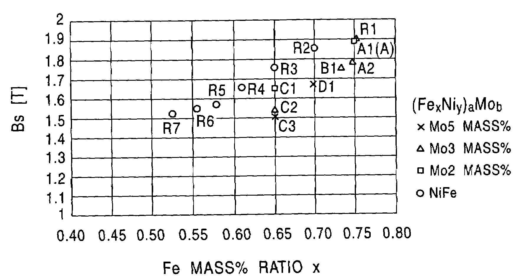
[0147]In an example of the present invention, FeNiMo alloys were formed in a plating bath by pulse current plating. For comparison, NiFe alloys were also formed by pulse current plating in a manner similar to that in the example.

[0148]The composition of the plating bath for the NiFe alloy is shown in Table 1, and the composition of the plating bath for the FeNiMo alloy is shown in Table 2.

[0149]

TABLE 1NiFeFe Ion Concentration (g / l) 1.0 to 3.3Ni Ion Concentration (g / l)10Fe Ion / Ni Ion0.10 to 0.33Boric Acid Concentration (g / l)25NaCl Concentration (g / l)25Saccharin Sodium Concentration (g / l) 2.0Pulse Current Density (mA / cm2)  9 to 19Duty Ratio of Pulse Current 0.3

[0150]

TABLE 2FeNiMoFe Mass % Ratio in Film 0.65 0.70 0.74 0.75Fe Ion Concentration (g / l) 2.1 2.4, 3.1 3.1 3.2, 3.3Ni Ion Concentration (g / l)10101010Fe Ion / Ni Ion 0.21 0.24, 0.31 0.31 0.32, 0.33No Ion Concentration (g / l) 0.03, 0.22, 0.25 0.12, 0.31 0.25 0.25, 0.27Boric Acid Concentration (g / l)25252525NaCl Concentration (g / l)25252...


PUM

PropertyMeasurementUnit
coercive forceaaaaaaaaaa
resistivityaaaaaaaaaa

Abstract

A soft magnetic film is formed which is represented by the formula (FexNiy)aMob, in which 0.65≦x≦0.75 and x+y=1 are satisfied when x and y are on a mass percent ratio basis, and 0<b≦5 and a+b=100 are satisfied when a and b are on a mass percent basis, and by using this soft magnetic film, a lower core layer and / or an upper core layer is formed. Accordingly, a saturated magnetic flux density of 1.6 T or more and a resistivity of 40 μΩ·cm or more can be obtained, and hence a thin film magnetic head having a small loss in a high frequency signal region can be provided.

Description

BACKGROUND OF THE INVENTION[0001]1. Field of the Invention[0002]The present invention relates to a soft magnetic film which is used, for example, as a core material of a thin film magnetic head and which is composed of an FeNiMo alloy having a high resistivity and a high saturated magnetic flux density, and to a thin film magnetic head using the soft magnetic film described above.[0003]2. Description of the Related Art[0004]In planar magnetic elements such as a thin film magnetic head or a thin film inductor, a NiFe alloy (permalloy) has been used as a magnetic material in many cases.[0005]Since, for example, the NiFe alloy mentioned above has relatively superior soft magnetic properties and is easily formed by plating, the NiFe alloy has become one of soft magnetic materials which are frequently used.[0006]However, concomitant with the recent trend toward a high frequency current of a planar magnetic element, an eddy current loss in a high frequency current region becomes a problem...

Claims


Application Information

Patent Timeline
Patent Type & Authority Patents(United States)
IPC IPC(8): H01F1/04G11B5/31G11B5/39H01F10/14
CPCG11B5/3909H01F10/14B82Y25/00G11B5/3109B82Y10/00G11B5/3903G11B5/3967G11B2005/3996G11B5/3163G11B5/3116G11B5/313G11B5/3146
Inventor YAZAWA, HISAYUKIKANADA, YOSHIHIRO
Owner TDK CORPARATION
Why Eureka
Try Eureka