Pathfinding system

a pathfinding and system technology, applied in the field of pathfinding systems, can solve the problems of not being aware of any system, not considering applying constraints to the path generation, and restricting the flexibility of the final route that is generated, so as to improve the user experien

Inactive Publication Date: 2007-08-23
BRITISH TELECOMM PLC
View PDF10 Cites 68 Cited by
  • Summary
  • Abstract
  • Description
  • Claims
  • Application Information

AI Technical Summary

Benefits of technology

[0050] Advantageously, the arrangements of the invention employ a technique which allows a content provider to define some initial points for navigation in a virtual world, allowing the content provider to influence the routes taken and the items of interest that can be visited by a user. The system then automatedly multiplies the number of points in a manner which will improve the user's experience along the subsequently generated path through the environment compared with only a limited set of originally defined navigation points.
[0051] In comparison with previously known systems in which a path through a virtual world is not constrained to specific navigation points, the embodiments of the invention provide improved processing during the actual pathfinding procedure. This is because no collision detection (ensuring the path avoids obstacles, etc) is required during pathfinding in the embodiments since all the new navigable nodes and links have been added on line of sight principles, and therefore by definition already avoid all the potential obstacles.
[0052] Additionally, these embodiments provide advantages over previous known systems such as the AA Routefinder which are necessarily limited to finding routes along specified predefined roads, etc. In contrast, in the embodiments, the user is able to navigate within all areas of the virtual world.

Problems solved by technology

However, Stout does not discuss the problems associated with constraining the angle differential between nodes.
However, Fredriksen does not consider applying constraints to the path generation such as angle-differential.
However the present inventors are not aware of any systems which enable routes to take account of less utilitarian preferences of users in anything less than a very rudimentary manner.
Also, such systems are necessarily restricted to calculating a route along predefined paths (i.e. where roads exist), and are therefore restricted in the flexibility of the final route that is generated.

Method used


Image

  • Pathfinding system
  • Pathfinding system
  • Pathfinding system

Examples


Embodiment Construction

[0065] There follows a detailed description of the preferred embodiments of the invention, which include a description of the best mode of the invention as currently contemplated by the inventors. Even where not explicitly described, it will be apparent to those skilled in the art that certain features of the invention can be replaced by their known equivalents, and the scope of the invention is intended to include such apparent equivalents to the described features where appropriate.

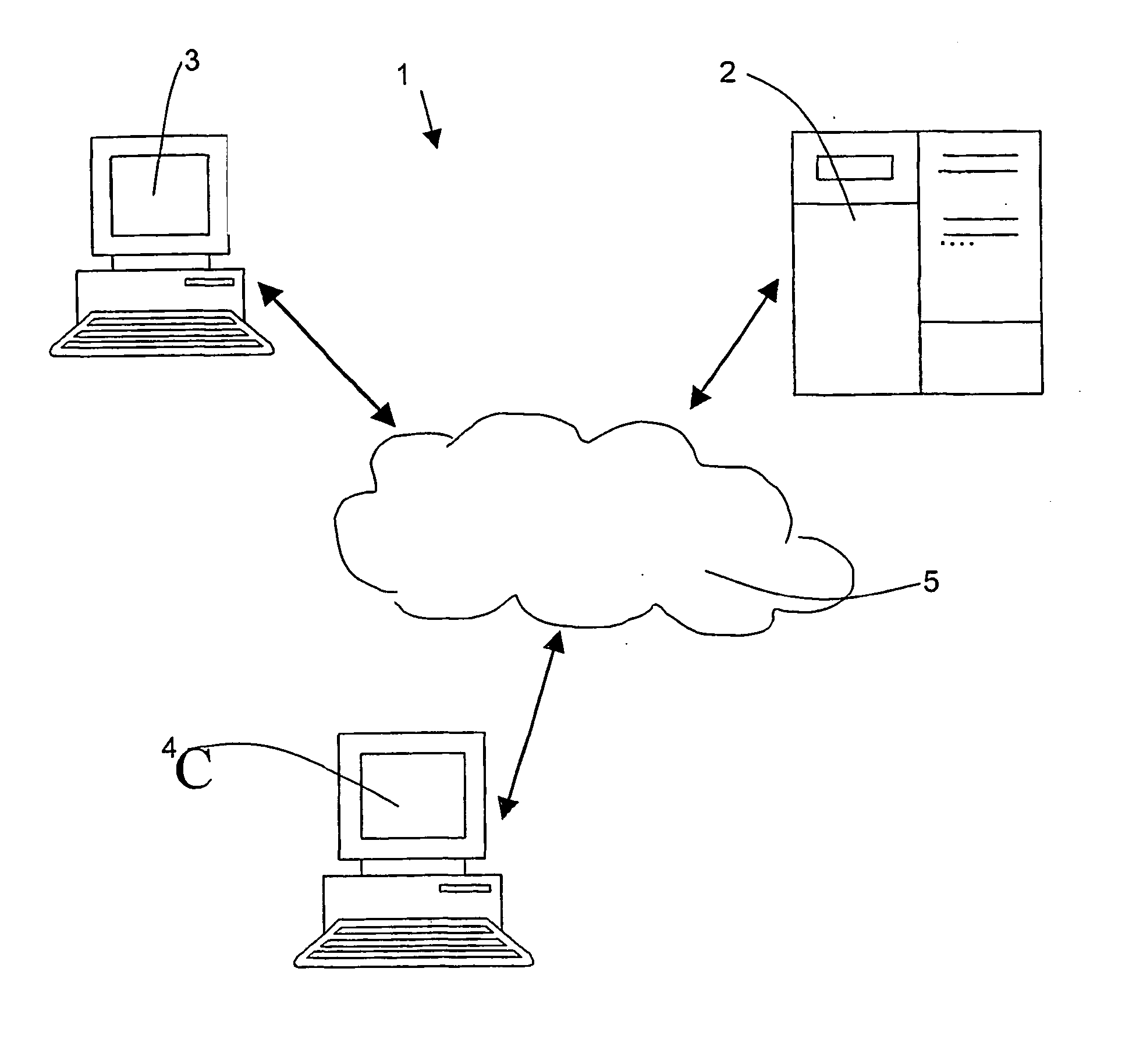
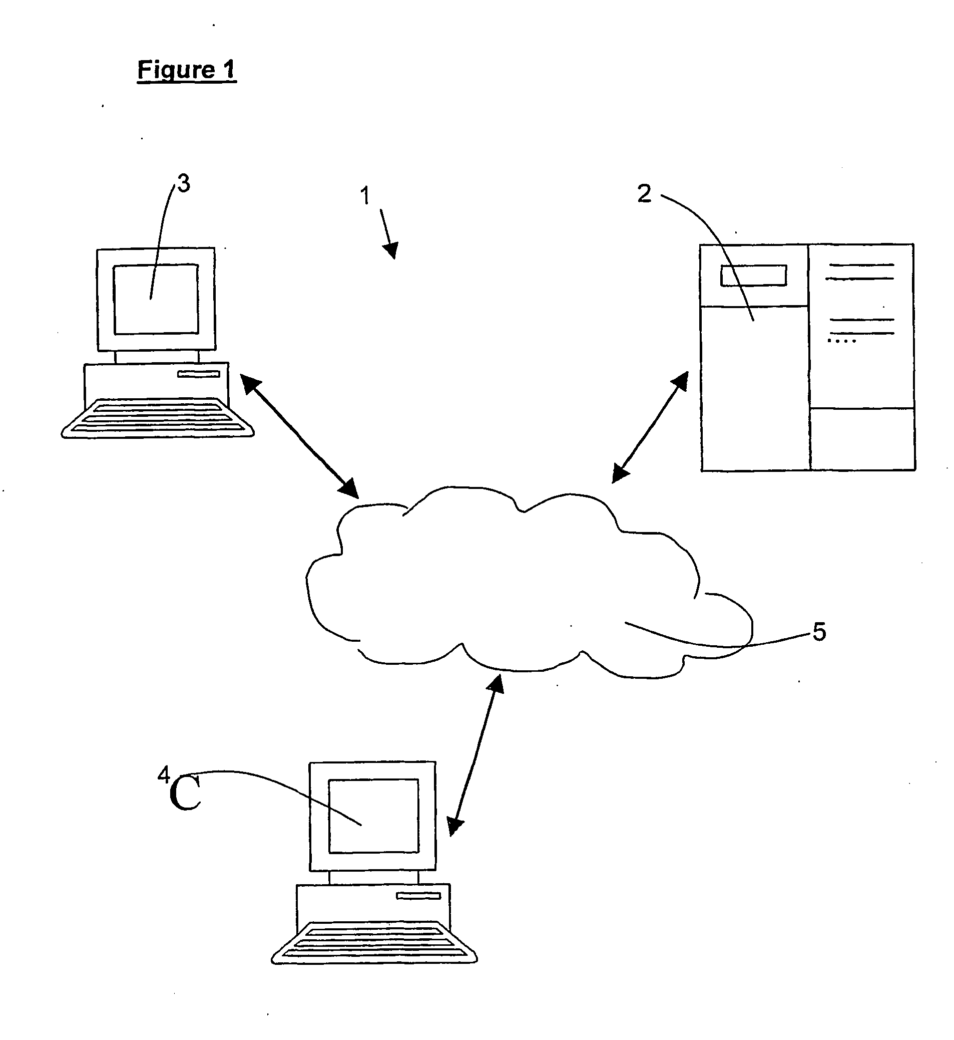
[0066]FIG. 1 illustrates a system 1 for creating, and allowing a user to navigate within, a virtual world. The system comprises a, server computer 2, accessible to a content provider (a human user who will input the specification for the virtual world) via terminal 3, and accessible to a user (desiring to view and navigate through the virtual world) via another terminal 4. In this particular embodiment, access from both terminals to the server 2 is through a general network 5, such as for example the i...


PUM


Abstract

A computer system is arranged to automatically calculate a path along nodes in a virtual world. After the co-ordinates for the virtual world environment have been initially defined (40), including nodes along which a path may travel, the system automatically increases the density of nodes in the environment up to a desired density. New nodes are added between each pair of nodes which have line of sight to each other (44 to 47), dramatically increasing the number of available links and nodes. This is repeated until a sufficient density of nodes is reached and no more nodes are being added (48 and 49).

Description

TECHNICAL FIELD [0001] The invention relates to a method and system for determining a path along a plurality of points in a virtual environment providing a representation of a real or virtual world. INTRODUCTION [0002] Systems in which 3-dimensional virtual reality environments (virtual worlds) are defined and created are becoming increasingly prevalent in the current technological age. Such computer systems are applicable in numerous commercial applications, such as for online tourist sites, fantasy worlds, gaming, architectural walk-throughs, estate agency (virtual tours of houses for sale), and many others. Typically, a virtual world might be defined by multiple x,y,z, co-ordinate sets which together map out an environment in three dimensions (x, y, and z axes). The topology of the virtual world can be defined by way in which the objects within the virtual world are organised within the three dimensions, i.e., by the spatial location of a number of nodal points (also referred to ...

Claims


Application Information

Patent Timeline
Patent Type & Authority Applications(United States)
IPC IPC(8): G01C21/30G06N5/00
CPCG06N5/003G06N5/01
Inventor TRIMBY, MARTIN W.GILLIES, MARCO FPBALLIN, DANIEL
Owner BRITISH TELECOMM PLC
Why Eureka
Try Eureka