
Form Made Of Thermoplastic Resin

Inactive Publication Date: 2007-08-30
KANA FURETSUKUSU KOOHOREESHON
View PDF7 Cites 3 Cited by
  • Summary
  • Abstract
  • Description
  • Claims
  • Application Information

AI Technical Summary

Benefits of technology

[0007] By using a thermoplastic resin containing an inorganic material, the hardness and softness of the form can be optimized and, further, heat resistance and impact resistance can be increased tremendously. Additionally, elongation and contraction due to changes in temperature can be reduced, and the shape can be stabilized. By forming an approximately rectangular reinforcement part narrower than the head part of a nail at the portion where the columnar reinforcement body is to be nailed, the nail driving surface of the form can be prevented from being dented when the form is nailed on such a columnar reinforcement body as a vertical frame, and the finish performance of concrete making contact with the form can be improved. Additionally, when not only an approximately rectangular reinforcement part but also an approximately truss shaped reinforcement part are combined, the deformation resistance to the pressure of concrete can be intensified while maintaining light weight of the form.
[0008] If a reinforcement part adjacent to the second reinforcement part is called a third reinforcement part, at least one sectional shape of two third reinforcement parts is rectangular in many cases. In this approximately rectangular third reinforcement part, it is desirable to form an oblique rib which serves as a diagonal line of this approximately rectangular shape, and the oblique rib (the diagonal line) expands from a forward side in the nail driving direction to a faraway side or an approximately X-shaped rib which serves as two diagonal lines of this approximately rectangular shape. Forming this rib enables to prevent the form from being dented by driving nails more highly.
[0009] It is recommended to form an indicated part on the first main plate in order to clarify a nail driving portion. This indicated part is capable of securely preventing the form from being dented by driving nails.
[0010] Further, it is desirable to form a surface layer made of a soft or semi-hard resin similar to the main plate at least on the surface of the first main plate facing poured concrete. This surface layer can protect the form from an impact of driving nails. Further, the release performance between the form and poured concrete can be improved.
[0011] Hollow parts (openings) between the partition plates may be filled with expanded resin bodies. Consequently, the strength and impact resistance of the form can be intensified while suppressing increase in weight of the form. Further, it is possible to eliminate the necessity of a cap for sealing the top and bottom opening of the form.

Problems solved by technology

However, it is thrown away after used repeatedly about 10 times, and is thus disadvantageous from viewpoint of cost.

Method used


Image

  • Form Made Of Thermoplastic Resin
  • Form Made Of Thermoplastic Resin
  • Form Made Of Thermoplastic Resin

Examples


Embodiment Construction

[0029] Hereinafter, the present invention will be described further in detail with reference to the accompanying drawings. Same reference numerals are attached to the same components so as to avoid duplicated description.

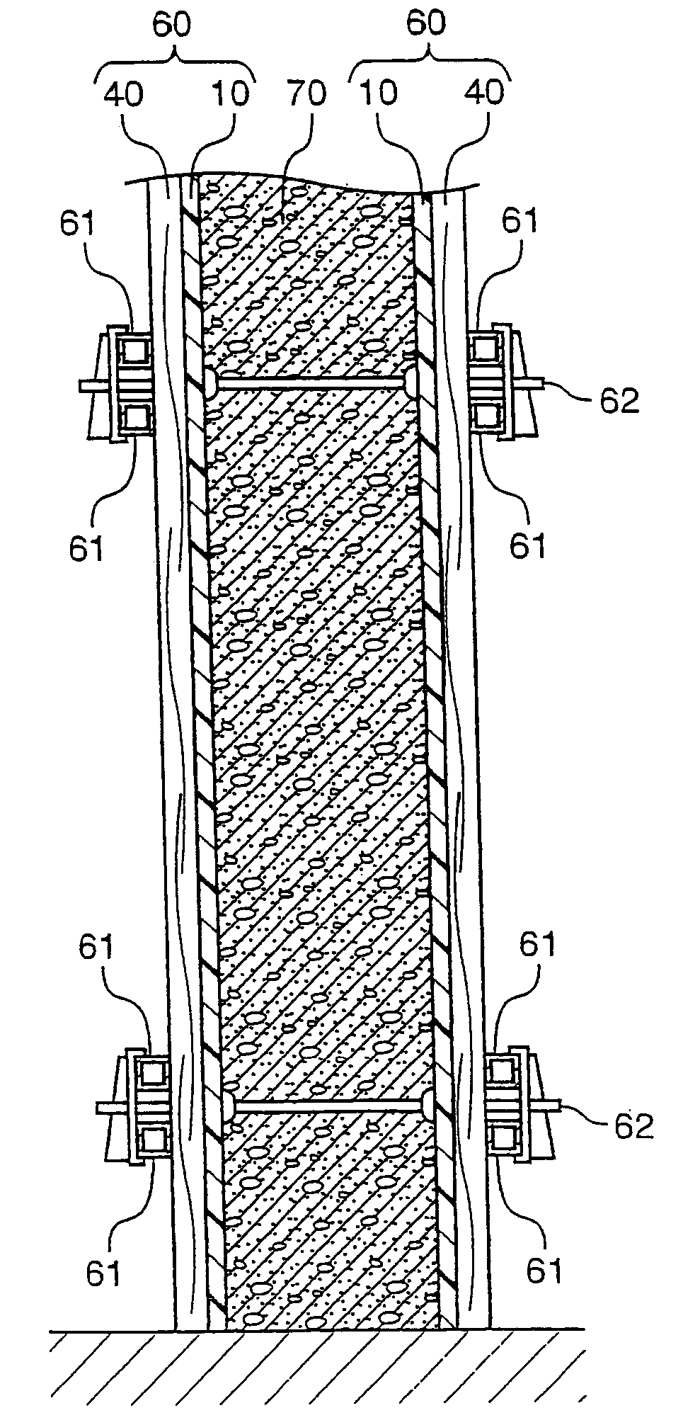
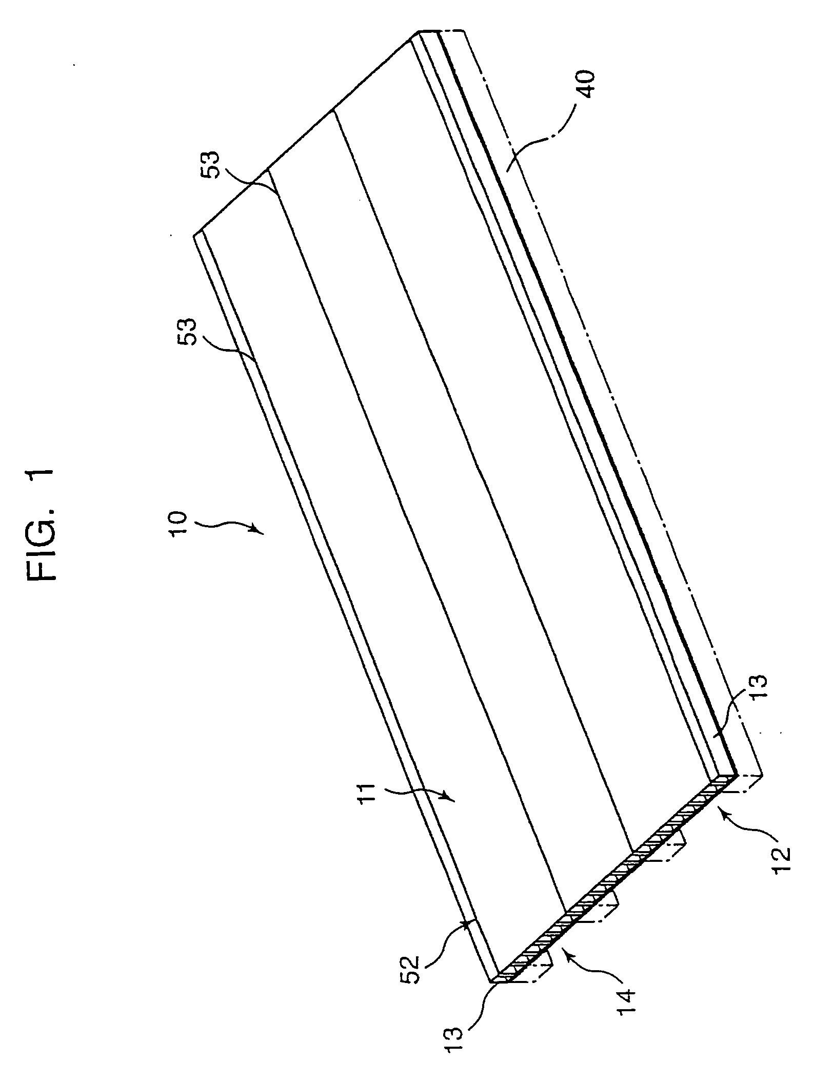
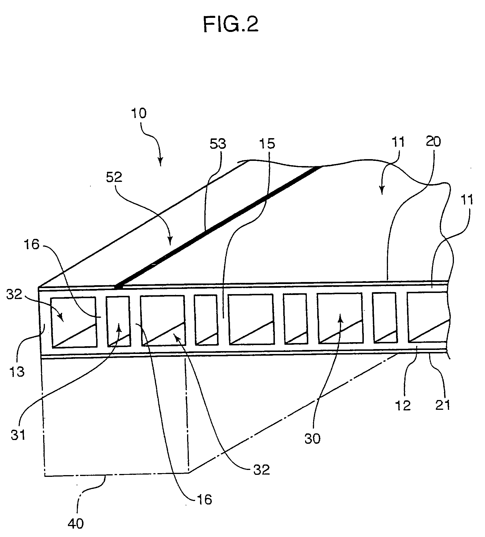
[0030]FIGS. 1, 2 show an example of the thermoplastic resin form of the present invention, used for concrete structure construction. FIG. 1 is a schematic perspective view of the thermoplastic resin form and FIG. 2 is a partially enlarged schematic perspective view of the form in FIG. 1. FIG. 3 is a partially broken enlarged schematic perspective view showing the use condition of the thermoplastic resin form of the present invention.

[0031] A form 10 made of thermoplastic resin shown in FIGS. 1, 2 includes a first main plate 11 whose plan view shape is approximately rectangular and which makes contact with poured concrete and a second main plate 12 having an approximately same plan view shape as this first main plate 11 and opposing the first main plate 11 with a p...


PUM

PropertyMeasurementUnit
Shapeaaaaaaaaaa
Widthaaaaaaaaaa
Thermoplasticityaaaaaaaaaa

Abstract

A form 10 for constructing a concrete structure is formed of a thermoplastic resin containing an inorganic material, and includes a first main plate 11 facing a poured concrete, a second main plate 12 opposing this first main plate, and partition plates 15, 16 extending between these first and second main plates. The partition plates 15 construct a plurality of first reinforcement parts 30 having at least one kind of cross sectional shape selected from an approximately rectangular shape and an approximately truss shape in a width direction from right to left. And the partition plates 16 construct a second reinforcement part 31 having an approximately rectangular cross sectional shape of a width capable of supporting an outer edge of a head part 51 of a nail 50 at a portion 52 where a columnar reinforcement body 40 for supporting a form is to be nailed.

Description

TECHNICAL FIELD [0001] The present invention relates to a thermoplastic resin form, that can be used as a permanent form disposed at a predetermined interval to construct a concrete structure, concrete being poured into that interval and hardened and the permanent form being left with that concrete structure as it is, or that can be used as a form removable after the concrete structure is completed and reusable repeatedly. BACKGROUND ART [0002] In the reusable form of the latter case, conventionally, a wooden form made of plywood has been used. However, it is thrown away after used repeatedly about 10 times, and is thus disadvantageous from viewpoint of cost. In recent years, a plastic form capable of being used about 30 times has been developed. [0003] A plastic form having plural openings of a rectangular or truss-like cross sectional shape, arranged in line along a width direction from right to left has been proposed (see, for example, FIG. 1 of JP-A 6-66021 (1994), FIG. 1 of JP-...

Claims


Application Information

Patent Timeline
IPC IPC(8): E04G11/06E04B2/86E04G9/05
CPCE04G9/05
Inventor KANAO, SHIGEKI
Owner KANA FURETSUKUSU KOOHOREESHON
Learn More