Furnace for Conditioning Preforms

Inactive Publication Date: 2011-06-09
KRONES AG
View PDF12 Cites 16 Cited by
  • Summary
  • Abstract
  • Description
  • Claims
  • Application Information

AI Technical Summary

Benefits of technology

[0011]In a preferred embodiment, the holding device comprises a bearing plate for a supporting ring embodied at the preform, a drive mechanism, in particular a circumferential toothing and / or a decentralized electric drive, being embodied at the holding device for rotating the preform. Thereby, the preform can be held at a region not to be conditioned to rotate the region to be conditioned in a defined manner and shield the region not to be conditioned from infrared radiation. Such an arrangement can be constructively particularly easily realized.
[0012]Preferably, the holding device comprises a receiving sleeve which surrounds the heating chamber at least partially circumferentially and is connected to the bearing plate by a releasable coupling, the drive mechanism being provided at the receiving sleeve. Thereby, the drive mechanism can be provided at a site that does not or only slightly restrict the accessibility of the heating chamber during loading or during the withdrawal of the preform. The preferably axially releasable coupling permits a quick exchange of the bearing plate and simultaneously permits a stable mount with respect to the rotational position of the preform.

Problems solved by technology

It is, however, a problem of such furnaces to selectively introduce a maximum proportion of the radiated thermal output into the preforms.
Here, however, a problem arises in that an opening region of the preform which is not to be deformed in the subsequent blow molding process must not be heated, or must not be heated to the same extent as the other wall sections of the preform.

Method used


Image

  • Furnace for Conditioning Preforms
  • Furnace for Conditioning Preforms
  • Furnace for Conditioning Preforms

Examples


first embodiment

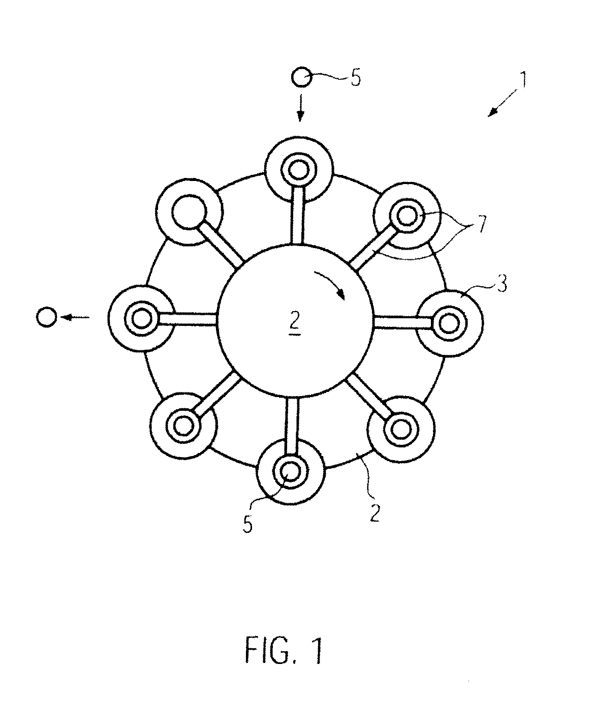
[0042]As can be seen in FIG. 1, the furnace 1 according to the disclosure comprises a heating wheel 2 with heating chambers 3 circumferentially uniformly distributed at the same for heating one preform 5 each, and holding devices 7 for holding the preforms 5. The holding devices 7 are embodied such that they can accept the preforms 5 from a (non-depicted) conventional infeed starwheel, such as a reduction starwheel, or transfer them to a (non-depicted) conventional discharge starwheel. For this, they can comprise, among other things, movable grippers and swiveling and / or lifting mechanisms. The holding device 7 can be moved in the direction of the main axis 5′ of the preform 5 represented in FIG. 3 with a lifting device 13 not represented more in detail to introduce the preform 5 into the heating chamber 3 or withdraw it from the heating chamber 3.

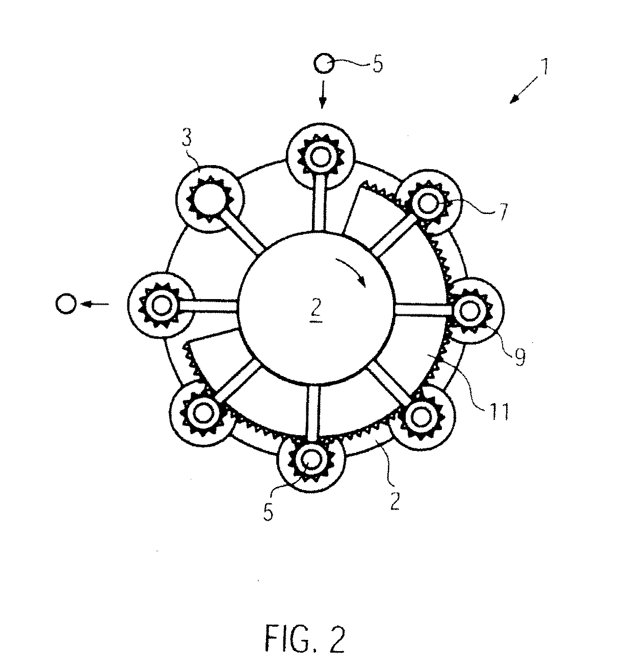
[0043]The second embodiment of the furnace 1 represented in FIG. 2 differs from the first embodiment in that the holding devices 7 additi...

second embodiment

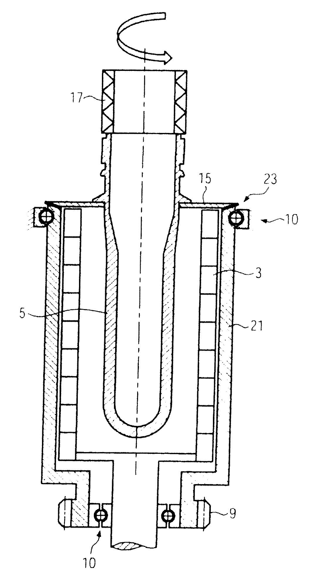
[0047]The drive mechanism 9 provided in the second embodiment is embodied at the bearing plate 15, for example as circumferential toothing. Furthermore, a bearing 10 for the bearing plate 15 is provided at the holding device 7 to permit rotation of the bearing plate 15 essentially about the longitudinal axis 5′ of the preform 5. Furthermore, the drive device 11 is indicated which is stationarily provided at the heating wheel 2 as indicated in FIG. 1. However, it would also be possible to design the drive device 11 in a decentralized manner, for example in the form of individual drive motors associated to the holding devices 7 or the heating chambers 3, respectively. Alternative types of a drive would also be conceivable, such as e.g. belt drives.

[0048]In the first embodiment, the driving elements 9, 11 shown in FIG. 3 are not required, the bearing 10 is preferably stationary.

[0049]The bearing plate 15 can be designed as fitting especially adapted to certain preforms 5 and be connect...


PUM

PropertyMeasurementUnit
aspect ratioaaaaaaaaaa
torqueaaaaaaaaaa
axis of rotationaaaaaaaaaa

Abstract

A furnace for conditioning preforms with several heating chambers rotating in a circle for heating one preform each with infrared radiation, and having holding devices for holding the preforms during heating, so that a section of the preform to be conditioned is essentially arranged in the heating chamber, and a section not to be conditioned is arranged outside the heating chamber. Accordingly, the section to be conditioned can be heated in a controlled and effective manner, and the section not to be conditioned can be protected from undesired heating.

Description

CROSS-REFERENCE TO RELATED APPLICATION[0001]The present application claims the benefit of priority of German Application No. 102009047536.2, filed Dec. 4, 2009. The entire text of the priority application is incorporated herein by reference in its entirety.FIELD OF THE DISCLOSURE[0002]The disclosure relates to a furnace for conditioning preforms, such as by infrared radiation, such as used in preparing molded containers used in bottling operations.BACKGROUND[0003]Containers to be manufactured by blow molding or stretch blow molding are shaped from so-called preforms that have to be heated to a desired process temperature before the actual blowing procedure. To be able to reshape, during blow molding, the rotationally symmetric preforms, which normally have standardized wall thicknesses, to containers having a certain shape and wall thickness, individual wall regions of the preform must be subjected to dosed heating in a furnace, preferably with infrared radiation. To this end, usual...

Claims


Application Information

Patent Timeline
Patent Type & Authority Applications(United States)
IPC IPC(8): F27D11/00F24C7/04
CPCB29B13/024B29C49/06B29C2035/0822B29C49/68B29C49/6436B29C2949/0715B29C49/681B29C49/685
Inventor WINZINGER, FRANKSCHONBERGER, WOLFGANGHOLZER, CHRISTIANSENN, KONRADWUTZ, ANDREAS
Owner KRONES AG
Why Eureka
Try Eureka