
Wheel having multiple tube frame structure

Inactive Publication Date: 2007-08-30
PRINCE SPORTS LLC
View PDF81 Cites 51 Cited by
  • Summary
  • Abstract
  • Description
  • Claims
  • Application Information

AI Technical Summary

Benefits of technology

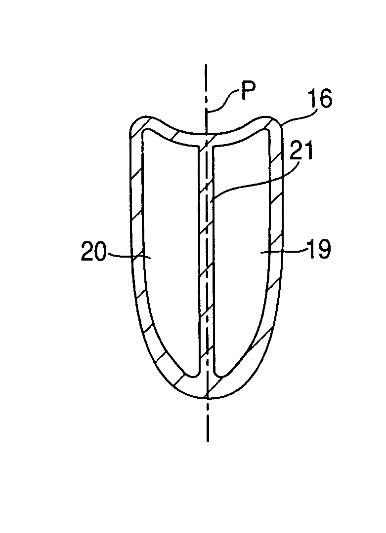
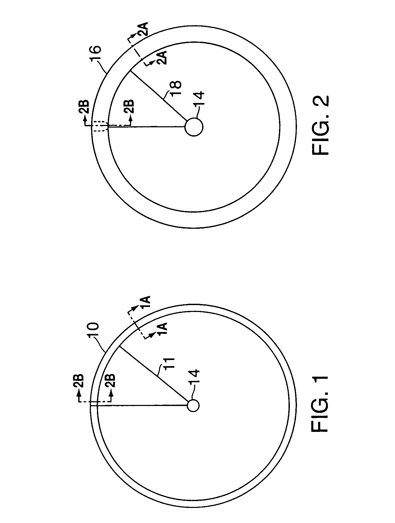
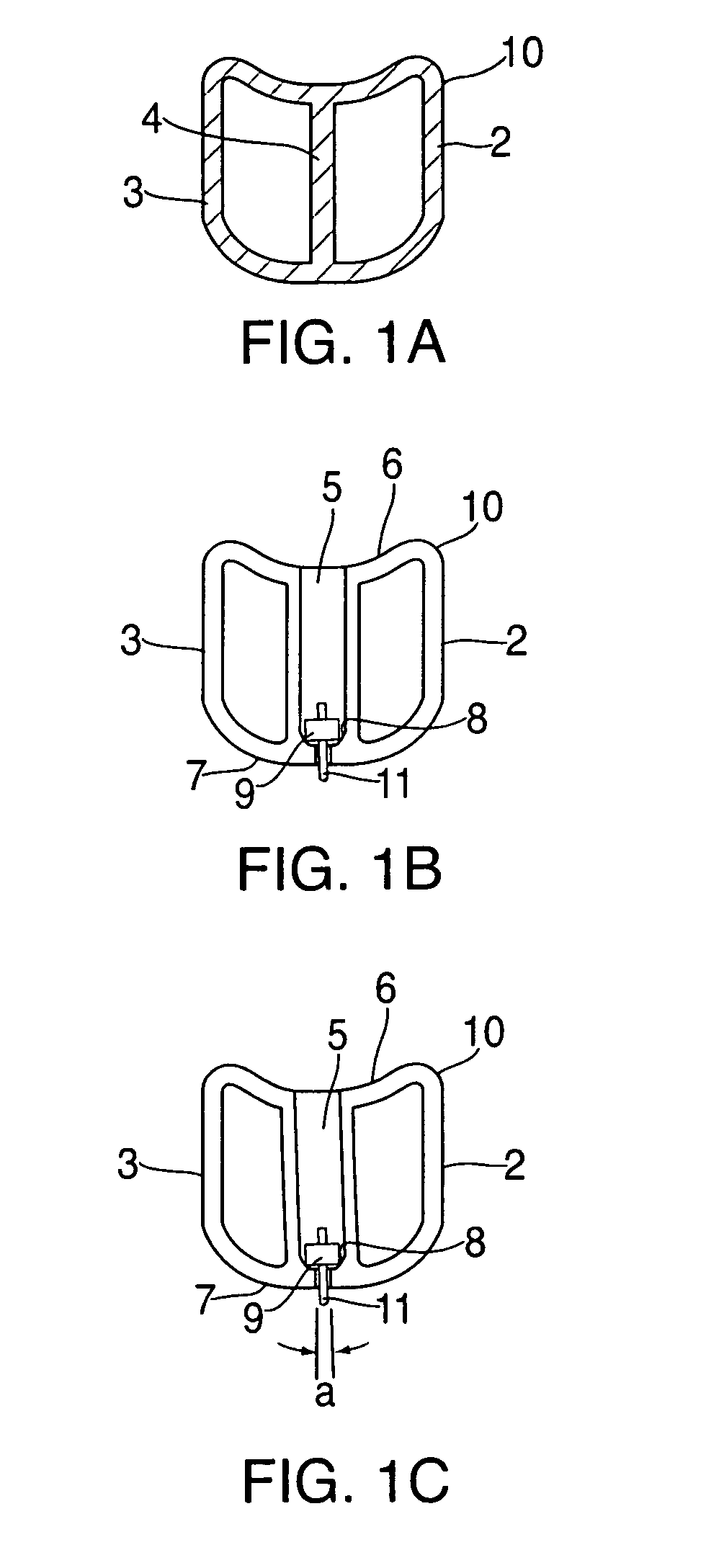
[0022] The present invention is for a wheel structure that is constructed using multiple tubes of composite prepreg materials that are molded into the various portions of the bicycle wheel such as the rim and spoke portions, wherein adjacent tubes are bonded together, i.e., fused, during molding along a common internal wall. Forming the rim and / or spokes with such a multiple tube design provides tailored stiffness, added strength, greater shock absorption, greater fatigue resistance, greater comfort, improved aerodynamics, improved spoke attachment means and improved aesthetics over the current prior art.

Problems solved by technology

The wheel presents a large frontal area and therefore is major contributor to aerodynamic drag.
In addition, the spokes can add significantly to the aerodynamic drag.
Furthermore, since there are two wheels, they can also contribute significantly to the overall weight of the bicycle.
It is very difficult to deliver both in a single technology or design.
These can result from the bicyclist taking a corner at high speeds, or by inducing high loads on the pedals while counteracting this torque with the handlebars.
There are vibrations resulting from “road buzz” by riding on a rough road.
Although this produces a very light weight design, having hollow spokes constructed of single composite tubes makes the wheel susceptible to compression buckling due to the thin walls of the tubes.
However, the hardness and therefore weight of the foam core would have to be substantial to resist this load.
This design utilizes hollow single tube spokes with a large cross sectional width dimension which makes them susceptible to buckling failure because of the thin sidewalls.
The design requires that holes are drilled to attach the spokes, and that the spokes attach to the thicker, stronger wall of the rim box because the fairing portion is too weak to support such loads.
For this reason, this design can feel unresponsive due to these deflections.
The drilling of holes can weaken a structure significantly.
This significantly weakens the structure and makes it more susceptible to failure.

Method used


Image

  • Wheel having multiple tube frame structure
  • Wheel having multiple tube frame structure
  • Wheel having multiple tube frame structure

Examples


Embodiment Construction

[0071] The present invention is designed to provide tailored stiffness, greater impact strength, greater shock absorption, greater fatigue resistance, greater aerodynamic effects, less vibrations, greater comfort, and improved aesthetics over the current prior art.

[0072] The wheel system according to the present invention substantially departs from the conventional concepts and designs of the prior art and in doing so provides an apparatus primarily developed for the purpose of maintaining light weight while improving stiffness, strength, shock absorption, aerodynamics as well as improved appearance. This combination of benefits has never been achieved before in wheel design.

[0073] The present invention uses multiple tubes which can be positioned and separated in local areas to form apertures at various locations to create unique performance advantages as well as a unique aesthetic appearance.

[0074] Designing a wheel using multiple tubes has numerous advantages. First of all, a c...


PUM


Abstract

A structure for a bicycle wheel includes at least two tubes for improving the stiffness, strength, aerodynamics and aesthetics of the wheel. The wheel may be designed as a rim type with traditional spokes, or as one piece wheel with attached spoke legs. Preferably, the tubes are separated at various locations to form apertures.

Description

BACKGROUND OF THE INVENTION [0001] The present invention is a composite wheel, and preferably a composite bicycle wheel made using a multitude of tubes fused together along their facing surfaces to provide an internal reinforcing wall as well as apertures, or “ports,” between the tubes to provide specific performance advantages. [0002] This invention relates to an improved structure for a composite bicycle wheel including the rim and spokes. In particular, the basis of the design is to take advantage of a structure using more than one reinforcing tube, which creates an internal reinforcing wall to improve strength and stability. In addition, these tubes can be separated in strategic locations and orientations to form apertures or ports between the tubes which act as double opposing arches which provide additional strength, stiffness and aerodynamic benefits. [0003] The weight of a performance bicycle is a critical feature in determining performance. The lighter the weight, the quick...

Claims


Application Information

Patent Timeline
IPC IPC(8): B60B21/06
CPCA63B59/0092B60B1/003B60B1/06B60B21/066B60B21/025B60B21/062B60B5/02A63B60/54
Inventor DAVIS, STEPHEN J.GAZZARA, ROBERTO
Owner PRINCE SPORTS LLC
Learn More