Method for prolonging life span of planar light source generating apparatus

Inactive Publication Date: 2007-08-30
IND TECH RES INST
View PDF8 Cites 4 Cited by
  • Summary
  • Abstract
  • Description
  • Claims
  • Application Information

AI Technical Summary

Benefits of technology

[0009] Accordingly, at least one objective of the present invention is to provide a method for prolonging the life span of a planar light source generating apparatus.
[0010] To achieve these and other advantages and in accordance with the purpose of the invention, as embodied and broadly described herein, the invention provides a planar light source generating apparatus. The planar light source generating apparatus not only has an emitting layer formed over the cathodes but has an emitting layer formed over the gates as well. To operate the planar light source generating apparatus, a DC square voltage is applied to the gates (or the cathodes) while the cathodes (or the gates) is electrically connected to a ground. When a detected current density drops to a certain ratio of a maximum current density, the external voltage supplying the aforementioned cathodes and gates are switched. In other words, the life span of the planar light source generating apparatus is prolonged after switching over the electron emission to the gates.

Problems solved by technology

Meanwhile, the electron current density (J) generated at the cathodes slowly decrease with time through repetitive operation until the situation is so deteriorated that the fluorescent layer no longer produces white light with sufficient brightness.

Method used


Image

  • Method for prolonging life span of planar light source generating apparatus
  • Method for prolonging life span of planar light source generating apparatus
  • Method for prolonging life span of planar light source generating apparatus

Examples


first embodiment

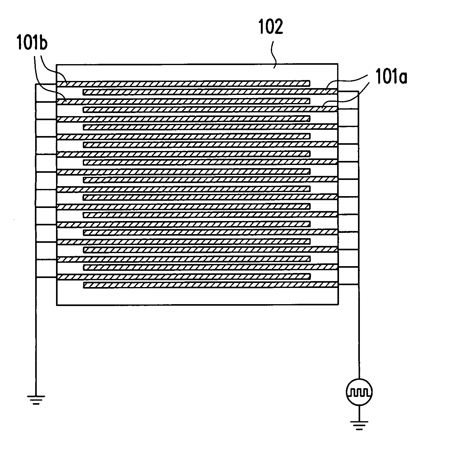
[0026]FIGS. 4 and 5 are circuit diagrams showing a DC square voltage applied to the cathodes and gates of a planar light source generating apparatus according to the present invention. As shown in FIGS. 4 and 5, the transparent glass substrate is labeled 102. The stripe cathodes 101b are all electrically connected to a ground while the stripe gates 101a are coupled to a DC square voltage having an amplitude of between 50V˜500V. Through this driving mode, the voltage difference between the cathodes 101b and the gates 101a is negative 50V˜500V so that the emitting layer 101c disposed on the stripe cathodes 101b can produce electrons.

[0027] In the meantime, a current sensor such as a current meter is installed in the planar light source generating apparatus 202 for measuring the current density (J) of the cathodes. Most of the electrons emitted from the cathodes bombard the fluorescent powder disposed on the fluorescent layer to produce white light. However, the current sensor picks up...

second embodiment

[0038] Obviously, in the present invention, when the planar light source generating apparatus with a prolonged life span is first used, the gates 101a can be electrically connected to the ground while the cathodes 101b can be electrically connected to a DC square voltage with amplitude of about 100V (not shown in the figure). After a specific time, the current sensor detects the electron current density attenuated to only 50% of the maximum value. Hence, the external supplying voltage between the cathodes and the gates are switched. In other words, the cathodes 101b are changed to be connected to the ground and the gates 101a are changed to be connected to a DC square voltage with about 100V amplitude. As a result, the life span of the apparatus is prolonged.

[0039] In summary, the method of extending the life span of a planar light source generating apparatus according to the present invention has at least one major advantage. The planar light source generating apparatus has emittin...


PUM


Abstract

A method for prolonging the life span of a planar light source generating apparatus is provided. The planar light source generating apparatus forms an emitting layer not only on a plurality of cathodes but on a plurality of gates as well. Moreover, an anode of the planar light source generating apparatus is electrically connected to a current sensor for reading out a maximum current density when the planar light source generating apparatus operates. To operate the planar light source generating apparatus, a DC square voltage is applied to the cathodes (or gates) while the gates (or the cathodes) are electrically connected to a ground. Once the current density detected by the current. sensor drops to a definite ratio of the maximum value, the external voltage supplying the aforementioned cathodes and the gates are switched. Thus, the life span of the planar light source generating apparatus is prolonged.

Description

CROSS-REFERENCE TO RELATED APPLICATION [0001] This application claims the priority benefit of Taiwan application serial no. 95101557, filed on Jan. 16, 2006. All disclosure of the Taiwan application is incorporated herein by reference. BACKGROUND OF THE INVENTION [0002] 1. Field of the Invention [0003] The present invention relates to a method for prolonging the life span of a light source generating apparatus. More particularly, the present invention relates to a method for prolonging the life span of a planar light source generating apparatus. [0004] 2. Description of the Related Art [0005] The principle of light emission in a field emission display device is based on the occurrence of electron emission at a tip of material in a vacuum environment due to there existing a strong electrical field. These field-emitted electrons leaving a cathode plate accelerate toward a positively charged anode plate and ultimately bombard with fluorescent material disposed thereon to produce light....

Claims


Application Information

Patent Timeline
IPC IPC(8): G09G3/10
CPCG09G3/3413G09G2320/043Y02B20/22H05B41/2806H05B41/24Y02B20/00
Inventor LIN, WEI-YILIN, BIING-NANHSIAO, MING-CHUNLIN, MING-HUNG
Owner IND TECH RES INST
Why Eureka
Try Eureka