Broadband antenna unit comprising a ground plate having a lower portion where both side corner portions are deleted

a technology of a ground plate and a lower portion, which is applied in the direction of elongated active element feed, resonant antennas, antenna earthings, etc., can solve the problems of difficult antenna planning for uwb, the presence or absence of carrier waves in uwb technology, and the difficulty of uwb including a lot of frequency components, so as to achieve the effect of improving the gain

Inactive Publication Date: 2007-08-30
MITSUMI ELECTRIC CO LTD
View PDF4 Cites 51 Cited by
  • Summary
  • Abstract
  • Description
  • Claims
  • Application Information

AI Technical Summary

Benefits of technology

[0021]It is therefore an object of the present invention to provide a broadband ...

Problems solved by technology

A crucial difference between a conventional radio technology and the UWB technology is the presence or absence of a carrier wave.
The antenna has a resonance frequency which is determined by its length, it is difficult for the UWB including a lot of frequency components to make the antenna for UWB resonate.
Accordingly, the wider the frequency band of the electric wave to be transmitted is, the more difficult it makes a plan for the antenna for UWB.
Inasmuch as t...

Method used


Image

  • Broadband antenna unit comprising a ground plate having a lower portion where both side corner portions are deleted
  • Broadband antenna unit comprising a ground plate having a lower portion where both side corner portions are deleted
  • Broadband antenna unit comprising a ground plate having a lower portion where both side corner portions are deleted

Examples


Embodiment Construction

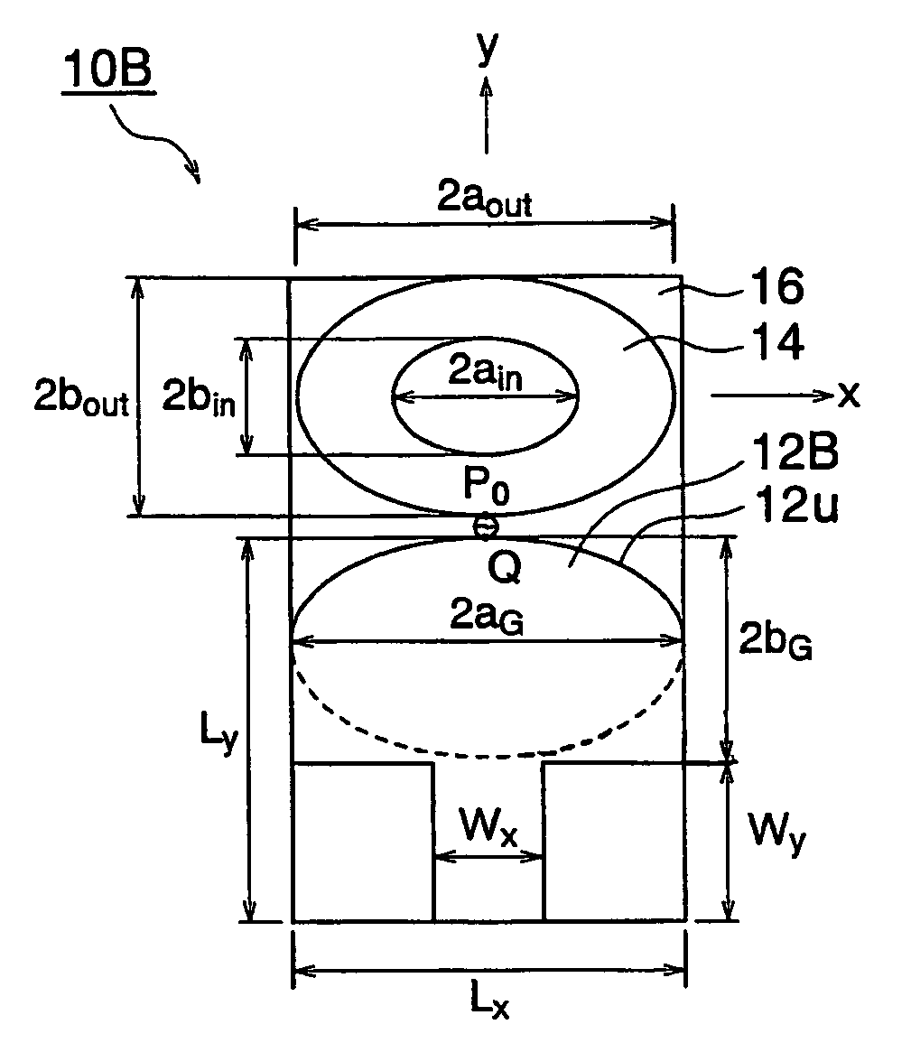
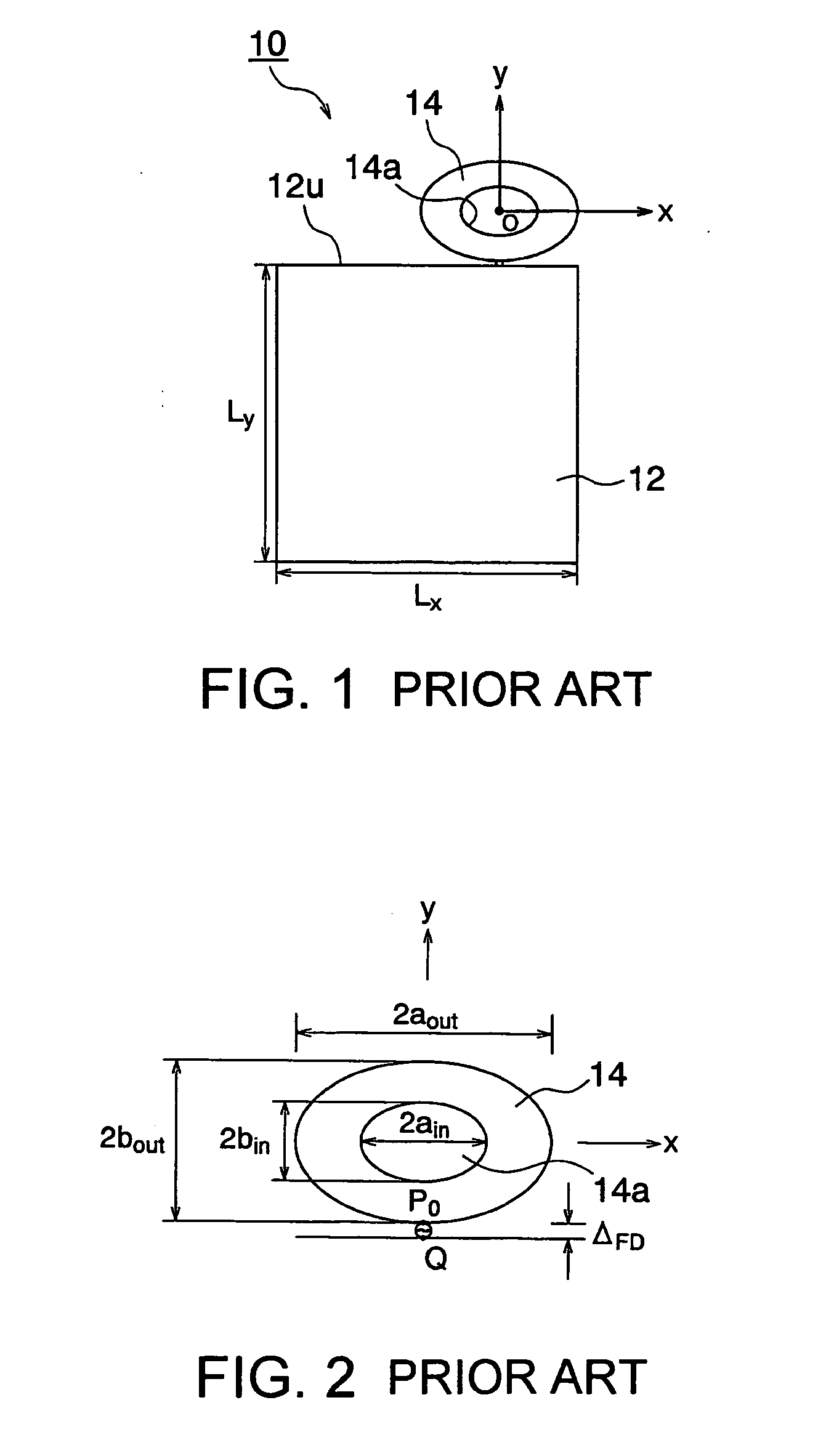
[0039]Referring to FIGS. 1 and 2, a first conventional broadband antenna unit 10 will be described at first in order to facilitate an understanding of the present invention. The illustrated broadband antenna unit 10 comprises an elliptically shaped ring broadband antenna disclosed in the above-mentioned first paper. FIG. 1 is a plan view of the broadband antenna unit 10 while FIG. 2 is an enlarged plan view showing a radiation element for use in the broadband antenna unit illustrated in FIG. 1

[0040]The broadband antenna unit 10 comprises a ground plate 12 and a radiation element 14. Herein, as shown in FIG. 1, the origin point is a center of radiation element 14, an x-axis extends laterally (in a width direction; a horizontal direction) and a y-axis extends longitudinally (up and down).

[0041]The ground plate 12 has a rectangular shape which has a x-direction length of Lx and a y-direction length of Ly. In the example being illustrated, the x-direction length Lx is equal to 45 mm and...


PUM


Abstract

In a broadband antenna unit having a ground plate and an elliptically shaped radiation element disposed at an upper portion of the ground plate in a plane where the ground plate extends, the ground plate has a semi-elliptically shaped upper edge and a lower portion where both side corner portions are deleted with a central portion left. The ground plate and the radiation element are formed on a substrate.

Description

[0001]This application claims priority to prior Japanese patent application JP 2006-53116, the disclosure of which is incorporated herein by reference.BACKGROUND OF THE INVENTION [0002]This invention relates to a broadband antenna unit and, more particular, to an antenna for an ultra wideband (UWB).[0003]The UWB technology means an ultra wideband radio technology like its name and is defined as any radio technology having a spectrum that occupies a bandwidth greater than 25 percent of the center frequency, or a bandwidth of at least 1.5 GHz. In a word, the UWB technology is technology for communicating using short pulses (normally each having a pulse width of 1 ns or less) of ultra wideband so as to start a revolution in radio technology.[0004]A crucial difference between a conventional radio technology and the UWB technology is the presence or absence of a carrier wave. The conventional radio technology modulates a sinusoidal wave having a frequency called the carrier wave using va...

Claims


Application Information

Patent Timeline
IPC IPC(8): H01Q1/38
CPCH01Q1/48H01Q9/40
Inventor NAKANO, HISAMATSUHATTORI, SATOSHIYAMAUCHI, JUNJIMIYOSHI, AKIRA
Owner MITSUMI ELECTRIC CO LTD
Why Eureka
Try Eureka