
Traffic information aggregating apparatus

Inactive Publication Date: 2007-08-30
HITACHI LTD
View PDF7 Cites 25 Cited by
  • Summary
  • Abstract
  • Description
  • Claims
  • Application Information

AI Technical Summary

Benefits of technology

[0007] This invention has been made in view of the above-mentioned problem, and therefore an object of this invention is to provide a network system in which an amount of data to be received by a monitor server is reduced.
[0009] According to the representative embodiment of this invention, the amount of data to be received by the monitor server can be reduced.

Problems solved by technology

Thus, a large amount of data is received by the monitor server, which causes a problem in system extensibility of a large scale network when the conventional traffic information monitoring system is used.

Method used


Image

  • Traffic information aggregating apparatus
  • Traffic information aggregating apparatus
  • Traffic information aggregating apparatus

Examples


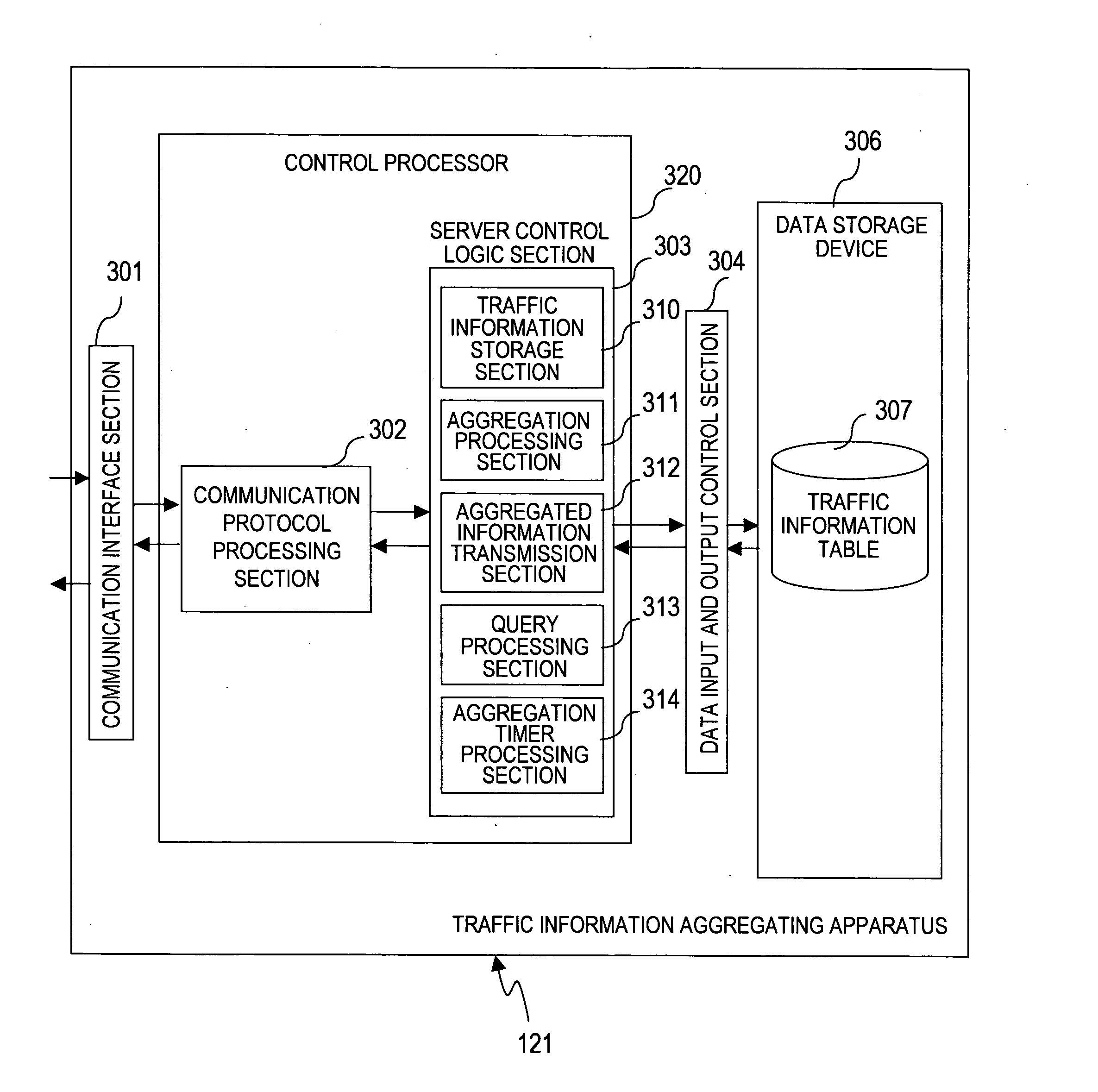
first embodiment

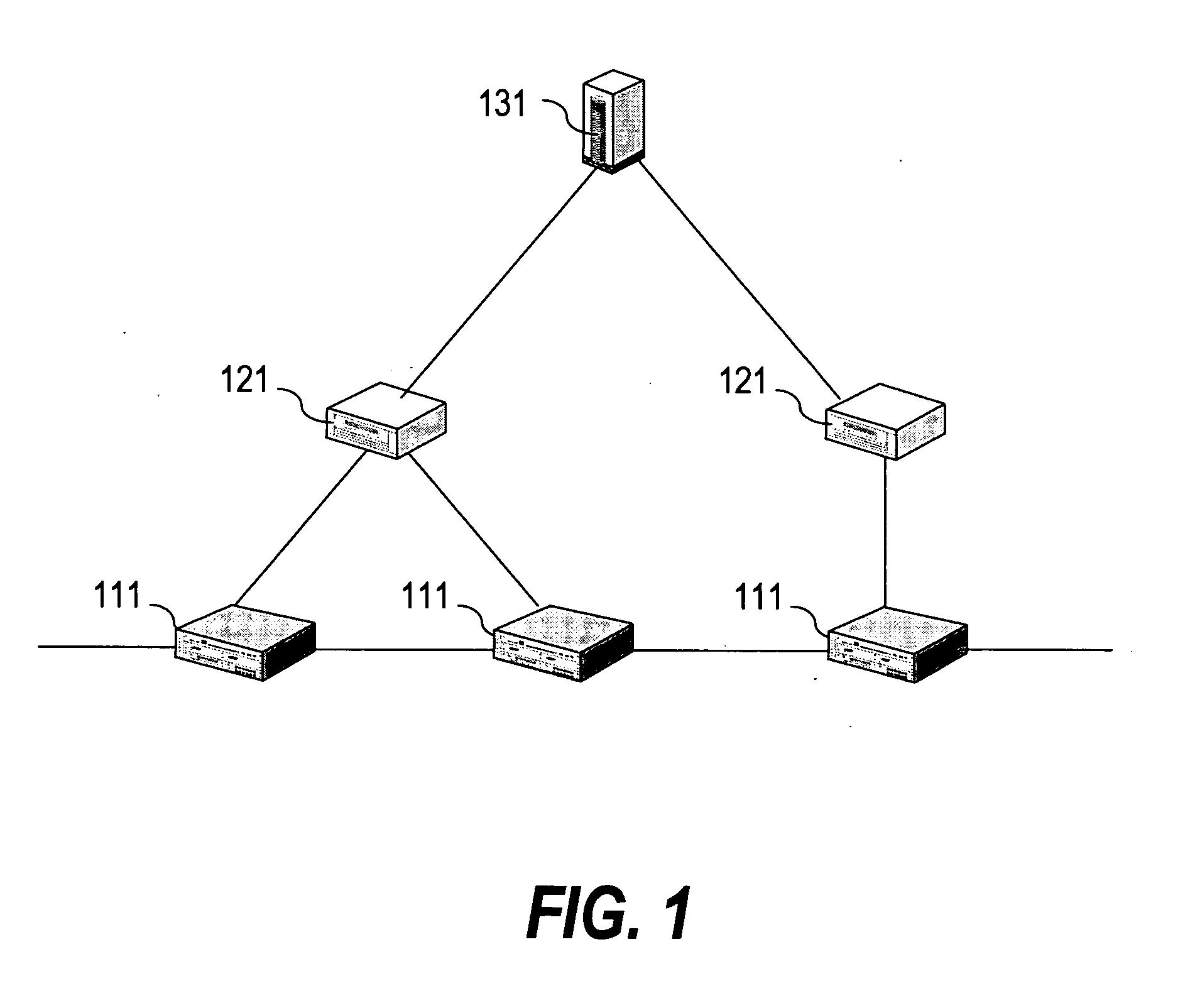
[0027]FIG. 1 is a block diagram of a configuration of a traffic information monitoring system according to a first embodiment of this invention.

[0028] The traffic information monitoring system includes a router 111, a traffic information aggregating apparatus 121, and a monitor server 131. The traffic information aggregating apparatus 121 is connected to one or more routers 111. The monitor server 131 is connected to one or more traffic information aggregating apparatuses 121.

[0029] The router 111 connects different networks to one another. In other words, the router 111 transfers data on a network, and transmits traffic information to the traffic information aggregating apparatus 121.

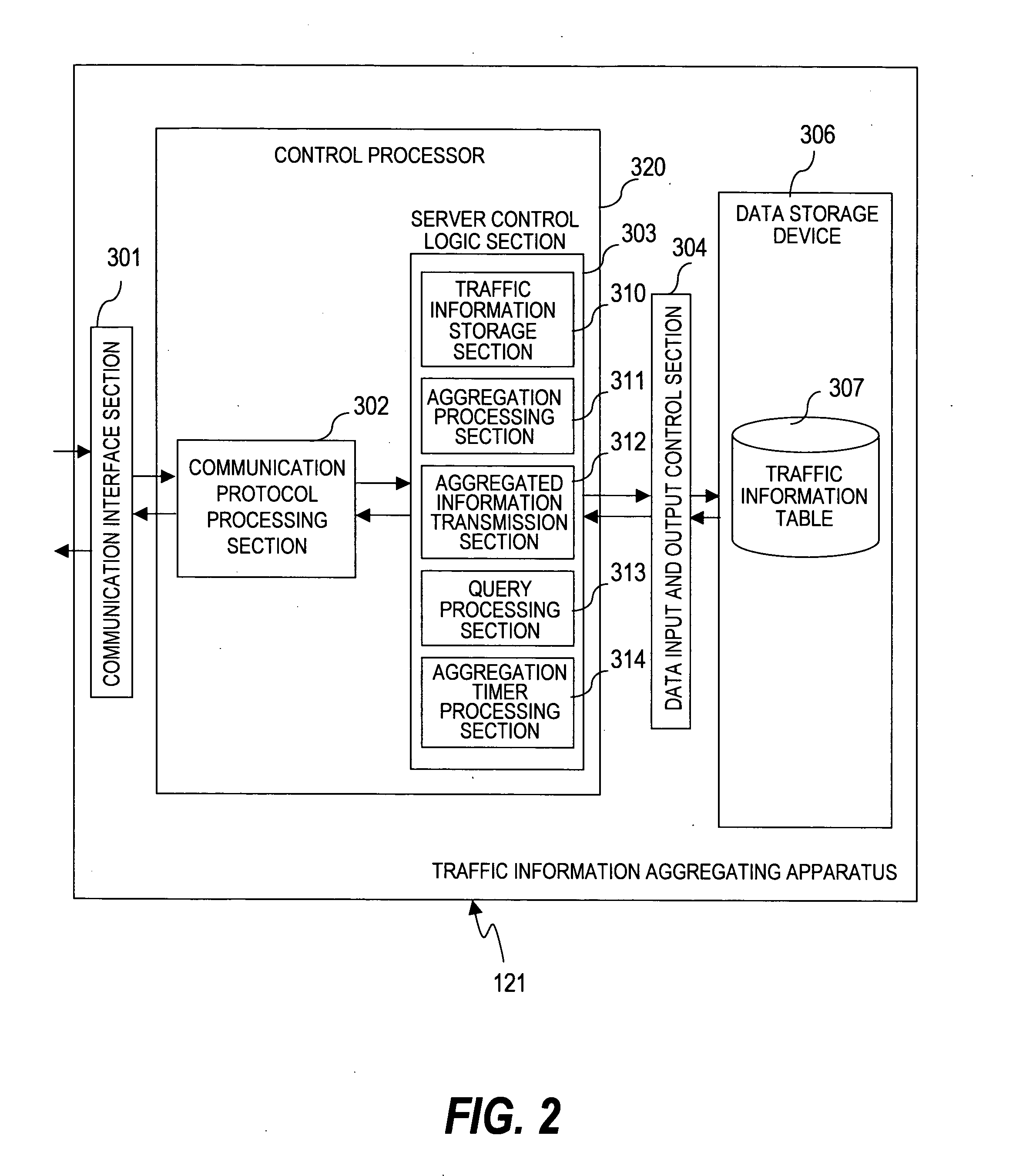
[0030] The traffic information aggregating apparatus 121 aggregates traffic information transmitted from the router 111. Details of the traffic information aggregating apparatus 121 will be described with reference to FIG. 2. The monitor server 131 is a computer including a CPU, a memory, and an int...

second embodiment

[0104] In a second embodiment of this invention, the traffic information aggregating apparatus 121 aggregates traffic information based on a destination IP address and a destination port number.

[0105] A configuration of a traffic information monitoring system of the second embodiment is the same as that of the traffic information monitoring system of the first embodiment shown in FIG. 1, so a description thereof is omitted. Further, an outline of processing in the traffic information monitoring system of the second embodiment is the same as that in the traffic information monitoring system of the first embodiment shown in FIG. 4, so a description thereof is omitted.

[0106]FIG. 10 is an explanatory diagram of an aggregation condition transmitted by the monitor server 131 according to the second embodiment of this invention.

[0107] The aggregation condition includes an aggregation key (AGGR_KEY), a value to be aggregated (AGGR_VALUE), and a type of an aggregation identifier (AGGR_ID_...


PUM


Abstract

Provided is a network system including a traffic information aggregating apparatus connected to a router for transferring data in a network, and a monitor server connected to the traffic information aggregating apparatus. In the network system, the traffic information aggregating apparatus receives traffic information from the router, assigns an aggregation identifier to the received traffic information, creates aggregated information by aggregating the traffic information based on the assigned aggregation identifier and by statistically processing the traffic information, transmits the created aggregated information and the assigned aggregation identifier to the monitor server, and retrieves, upon reception of a retrieval request including the aggregation identifier from the monitor server, requested traffic information from the received traffic information, based on the aggregation identifier included in the received retrieval request. Accordingly, an amount of data received by the monitor server can be reduced.

Description

CLAIM OF PRIORITY [0001] The present application claims priority from Japanese patent application JP2006-50154 filed on Feb. 27, 2006, the content of which is hereby incorporated by reference into this application. BACKGROUND OF THE INVENTION [0002] This invention relates to a network system including a traffic information aggregating apparatus and a monitor server, and more particularly to a technique of aggregating traffic information. [0003] A conventional traffic information monitoring system includes a router, a traffic information aggregating apparatus, and a monitor server. The traffic information aggregating apparatus is connected to the router. The monitor server is connected to the traffic information aggregating apparatus. [0004] The router transmits traffic information to the traffic information aggregating apparatus. The traffic information aggregating apparatus receives the traffic information from the router and stores the received traffic information in the form of a...

Claims


Application Information

Patent Timeline
IPC IPC(8): H04L12/26H04L12/70
CPCY02B60/33H04L43/026Y02D30/50
Inventor MATSUBARA, DAISUKEFUKUDA, YASUSHIKIYOTO, SATOSHIBABA, TOMOHIRO
Owner HITACHI LTD
Learn More