
Natural circulation boiling water reactor

a technology of boiling water and boiling water, which is applied in the direction of nuclear reactors, nuclear elements, greenhouse gas reduction, etc., can solve the problems of reducing the reactivity of the core, and achieve the reduction of the thermal margin in the core, the reduction of the reactivity of the core, and the effect of increasing the thermal margin

Inactive Publication Date: 2007-08-30
HITACHI-GE NUCLEAR ENERGY LTD
View PDF3 Cites 16 Cited by
  • Summary
  • Abstract
  • Description
  • Claims
  • Application Information

AI Technical Summary

Benefits of technology

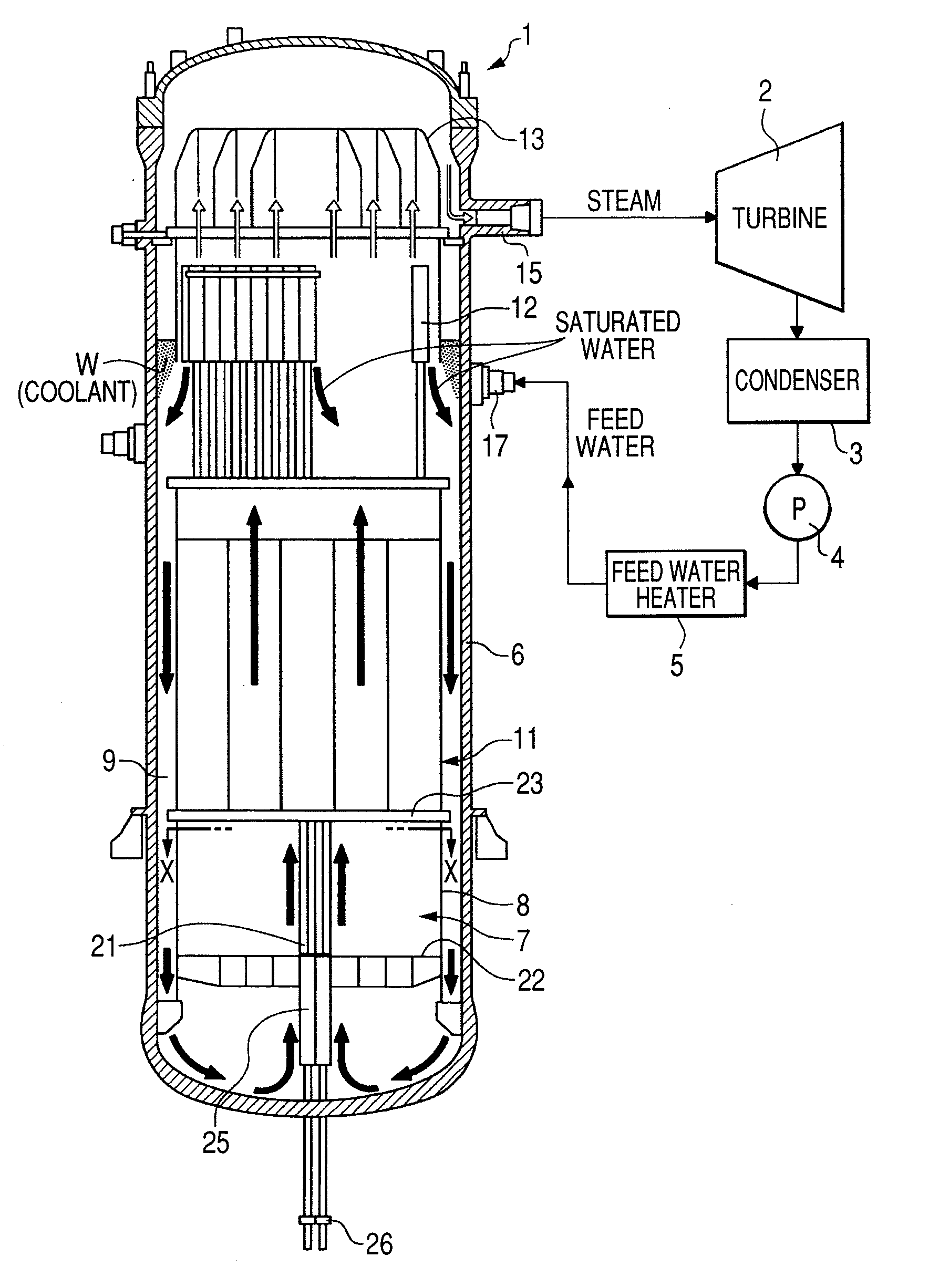
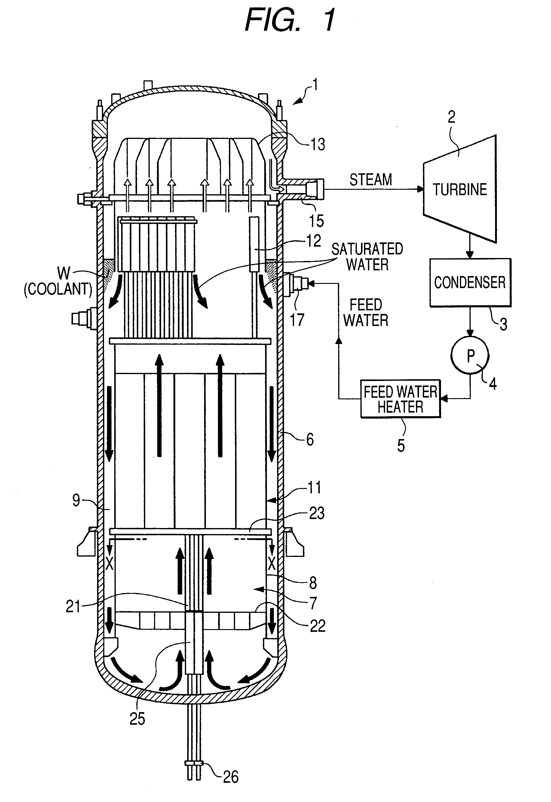
[0005]According to the prior art technology for the natural circulation boiling water reactor, by increasing the coolant flow rate to the outermost region, there is the effect that the power of the fuel assemblies at the outermost region is increased and the power distribution in a radial direction of the core is flattened. However, on the other hand, there are problems in that the thermal margin in the core is reduced due to the increase in the temperature of the coolant that re-circulates in the core, and the reactivity of the core is reduced.
[0006]The object of the present invention is to provide a natural circulation boiling water reactor in which the power distribution in a radial direction of the core is flattened, and in which it is possible to increase the thermal margin.
[0008]According to the present invention, the coolant flow rate distribution to each fuel assembly arranged in the core, and thus power distribution in a radial direction of the core is flattened and it becomes possible to increase the thermal margin.

Problems solved by technology

However, on the other hand, there are problems in that the thermal margin in the core is reduced due to the increase in the temperature of the coolant that re-circulates in the core, and the reactivity of the core is reduced.

Method used


Image

  • Natural circulation boiling water reactor
  • Natural circulation boiling water reactor
  • Natural circulation boiling water reactor

Examples


first embodiment

[0038]The following is a description of the first embodiment of the present invention. FIG. 5 shows the fuel assemblies loaded in the core in only the region which is the upper left quarter shown in FIG. 4. The region not shown in FIG. 5 can be considered to be a figure in which the region in FIG. 5 is rotated 90°, 180°, and 270° clockwise around the core plane center 40 and thus for simplification, a quarter of the diagram is described.

[0039]As shown in FIG. 5, in the first embodiment, the core 7 is divided into three regions in a radial direction. That is to say, the core 7 is divided into three regions including one layer (referred to as an outermost region hereinafter) 51 at the outermost side of the core 7, two-three layers (referred to as an outer region hereinafter) 52 inside the outermost region 51 and other layers (referred to as an inner region hereinafter) 53 inside the outer region 52. The outermost region 51 is first region, the outer region 52 is second region and the ...

second embodiment

[0050]The following is a description of the second embodiment of the present invention. FIG. 6 shows the fuel assemblies loaded in the core in only the region which is the upper left quarter shown in FIG. 4. It is to be noted that the method for viewing the diagram is the same as in the first embodiment and thus a description thereof has been omitted.

[0051]As shown in FIG. 6, in the second embodiment, the core 7 is divided into three regions in a radial direction. That is to say, the core 7 divided into three regions including one layer (outermost region) 61 at the outermost side of the core 7, two-three layers (outer region) 62 inside the outermost region 61, and other layers (inner region) 63 inside the outer region 62. The outermost region 61 is first region, the outer region 62 is second region and the inner region 63 is third region. It is to be noted that as is the case in the first embodiment, the number of layers in each region is not limited by that shown in the drawing and...

third embodiment

[0062]The following is a description of the third embodiment of the present invention. FIG. 7 shows the fuel assemblies loaded in the core in only the region which is the upper left quarter shown in FIG. 4. It is to be noted that the method for viewing the diagram is the same as in the first embodiment and thus a description thereof has been omitted.

[0063]As shown in FIG. 7, in the third embodiment, the core 7 is divided into three regions in a radial direction. That is to say, the core 7 is divided into three regions including one layer (outermost region) 71 at the outermost side of the core 7, two-three layers (outer region) 72 inside the outermost region 71 and other layers (inner region) 73 inside the outer region 72. The outermost region 71 is first region, the outer region 72 is second region and the inner region 73 is third region. It is to be noted that as is the case in the first embodiment, the number of layers in each region is not limited by that shown in the drawing and...


PUM


Abstract

A core disposed in a reactor pressure vessel includes one layer (an outermost region) at an outermost side of the core, two-three layers (an outer region) inside the outermost region and other layers (an inner region) inside the outer region. Fuel assemblies arranged in the core are supported by fuel supports having orifice. Orifice pressure loss coefficient of the orifice in the outermost region is set to be maximum and the orifice pressure loss coefficient of the orifice in the outer region is set to be minimum such that the flow rate of the coolant W for each fuel assembly in the outermost region is lowest and that for each fuel assembly in the outer region is highest. In the core of the natural circulation boiling water reactor, the reactor power distribution in a radial direction is flattened, and it is possible to increase the thermal margin.

Description

CLAIM OF PRIORITY[0001]The present application claims priority from Japanese application serial no. 2006-053088, filed on Feb. 28, 2006, the content of which is hereby incorporated by reference into this application.BACKGROUND OF THE INVENTION[0002]The present invention relates to a natural circulation boiling water reactor.[0003]In a forced circulation boiling water reactor, core flow rate of the coolant for cooling fuel assemblies loaded in a core is determined by output of a pump. The flow rate distribution to each fuel assembly is set by pressure loss coefficient of the orifice provided so as to correspond to each fuel assembly. Technology has been disclosed in which setting of the orifice pressure loss coefficient for the fuel assemblies, for example, may be such that the orifice pressure loss coefficient is larger in the outermost region of the core than the inner region near the center of the core, and thus the coolant flow rate distribution to the each fuel assembly is optim...

Claims


Application Information

Patent Timeline
Patent Type & Authority Applications(United States)
IPC IPC(8): G21C1/04
CPCG21C1/084G21C7/005G21Y2002/201Y02E30/39G21Y2004/403Y02E30/31G21Y2004/30Y02E30/30
Inventor ISHII, KAZUYAAOYAMA, MOTOOHINO, TETSUSHI
Owner HITACHI-GE NUCLEAR ENERGY LTD
Learn More