
Auxiliary exhaust structure and method therfor

a technology of exhaust structure and auxiliary exhaust, which is applied in the direction of ventilation system, heating type, stove or range, etc., can solve the problems of not fully considering the upward and outward diffusion of pollution source, the size of the fan device, and the remaining pollution source may escape everywhere, so as to facilitate exhausting and enhance the effect, pollution source can be successfully exhausted

Inactive Publication Date: 2007-08-30
ACXING INDAL CO LTD
View PDF11 Cites 50 Cited by
  • Summary
  • Abstract
  • Description
  • Claims
  • Application Information

AI Technical Summary

Benefits of technology

[0014] To achieve these and other advantages and in accordance with the present invention, as embodied and broadly described herein. The auxiliary exhaust structure comprises an exhaust hood and an air feeder. The exhaust hood disposed corresponding to the workstation has a suction port for sucking a pollution source, and a deflector extending along the periphery of the suction port for guiding the pollution source. The air feeder generates air flows flowing along the deflector towards the suction port. When the pollution source is sucked by the exhaust device to flow from the workstation to the suction port, the air feeder guides the remaining pollution source at the deflector to flow towards the suction port, so as to facilitate the exhausting.
[0015] Moreover, to further enhance the effect of the present invention, in the present invention, an exhauster mentioned in the above granted patent proposed by the author of the present invention (U.S. Pat. No. 6,752,144) can be disposed at the outer edge of the workstation. The exhauster can generate air curtains facing the exhaust hood, such that when the pollution source rises from the workstation, it is guided by the air curtains to flow towards the exhaust hood, and the air curtains prevent the pollution source from diffusing outward. Besides, when the pollution source flows to the deflector, the air feeder can guide the pollution source to flow to the suction port. As such, the pollution source can be successfully exhausted.
[0016] Furthermore, the present invention also discloses an auxiliary exhaust method. First, an exhaust hood is disposed corresponding to the workstation, and the suction port of the exhaust hood is employed to suck the pollution source. Then, a deflector is disposed, extending along the periphery of the suction port. Moreover, an air feeder is disposed to generate air flows, so as to guide the pollution source to flow from the deflector to the suction port via the air flows, thereby facilitating the exhausting.
[0017] According to the auxiliary exhaust structure and the method therefor disclosed by the present invention, the pollution source falls in the surrounding area during the exhaust process instead of diffusing outward. Therefore, the required exhaust effect is ensured and the pollution source is more likely to flow towards the suction port, so the gathering effect is enhanced to make it easier for the exhaust hood to trap the pollution source. Beside, the flow of the pollution source is smoothed, and the direction of the pollution source is not easily interfered by the guiding air flows or environmental side wind. Further, the required guiding air flows can be regulated to meet the auxiliary exhaust effect without taking too much space.

Problems solved by technology

In addition, the remaining pollution source may escape everywhere as the pollution source is gathered simultaneously around the inlet.
However, the prior arts disclosed above fail to entirely take into consideration the upward and outward diffusion of the pollution source when sucked by the exhaust device, the size of the fan device for guiding the pollution source, the interference on the direction of the pollution source flowing towards the exhaust device under the influence of the guiding side wind, and the non-conformity of the exhaust direction of the exhaust device and the flow direction of the pollution source.

Method used


Image

  • Auxiliary exhaust structure and method therfor
  • Auxiliary exhaust structure and method therfor
  • Auxiliary exhaust structure and method therfor

Examples


first embodiment

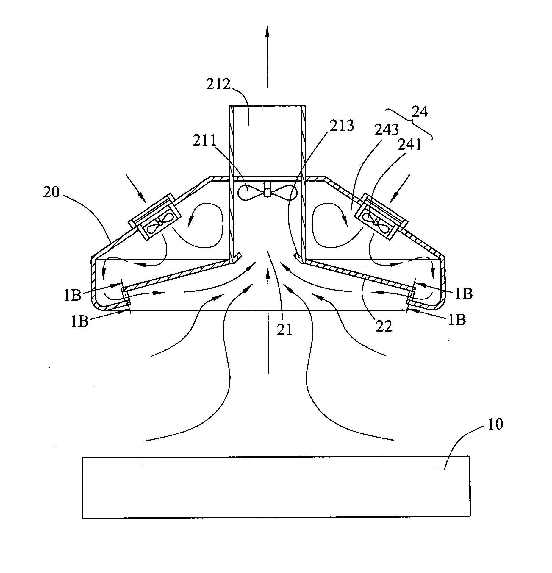
[0028] the auxiliary exhaust structure of the present invention is shown in FIG. 1A, comprising a workstation 10 and an exhaust hood 20 disposed correspondingly.

[0029] As shown in FIGS. 1A, 1B, and 3, the exhaust hood 20 comprises a suction port 21 and a deflector 22 extending along the periphery of the suction port 21. The deflector 22 forms an angle with the periphery of the suction port 21, such that the deflector 22 is tilted relative to the periphery of the suction port 21. An air feeder 24 disposed at one side of the deflector 22 mainly comprises a fan 241 and an air outlet 242, wherein one end of the air outlet 242 is connected to the fan 241 and the other end of the air outlet 242 is disposed at the edge of the deflector 22. Therefore, the air outlet 242 can receive the air flow generated by the fan 241 and guide the air flow to the deflector 22. In addition, the air outlet 242 is surrounding the edge of the deflector 22 to guide the air flow flowing all over along the defle...

second embodiment

[0032] the auxiliary exhaust structure according to the present invention is shown in FIG. 2, comprising a workstation 10 and an exhaust hood 20 disposed correspondingly. To further enhance the effect of the invention, the workstation 10 further comprises an exhauster 40 disposed at the outer edge of the workstation 10 and generating air curtains 41 facing the exhaust hood 20. The air curtains 41 facing the suction port 21 of the exhaust hood 20 can form air walls (only one air wall formed by the air curtains 41 of the exhauster 40 is shown as a representative). The air walls are used to make the air curtains 41 generated by the exhauster 40, the workstation 10, and the exhaust hood 20 together constitute a surrounding space 42 for preventing the pollution source diffusing outward

[0033] Afterward, as shown in FIGS. 1A and 2, the exhaust hood 20 is used to exhaust the pollution source of the workstation 10. The suction port 21 is used to suck the pollution source, while the deflector...

third embodiment

[0034] As shown in FIG. 4, it is the auxiliary exhaust structure according to the present invention, wherein the deflector 22 is parallel to the periphery of the suction port 21. The pollution source near the deflector 22 is guided to the suction port 21 by the air feeder 24. The air feeder 24 generates air flows by means of the fan 241 and the air flows are sent out from the air outlet 242 with a plurality of ribs. The other end of the air outlet 242 is disposed at the edge of the deflector 22 so as to make the air flows flow along the deflector 22 towards the suction port 21. As such, the pollution source guided by the air flows also flows from the periphery of the deflector 22 towards the suction port 21. Then, the pollution source is sucked into the suction port 21 and exhausted through the exhaust channel 212.

[0035] As shown in FIGS. 5 and 6, the exhaust hood 20 corresponding to the workstation 10 is disposed and the suction port 21 of the exhaust hood 20 is employed to suck th...


PUM


Abstract

An auxiliary exhaust structure and method therefor are used to exhaust a pollution source of a workstation. The auxiliary exhaust structure includes an exhaust hood and an air feeder. The exhaust hood disposed corresponding to the workstation has a suction port for sucking the pollution source and a deflector extending along the periphery of the suction port for guiding the pollution source. The air feeder generates air flows flowing along the deflector towards the suction port for guiding the pollution source. Therefore, during the exhausting of the pollution source, the gathering effect of the pollution source flowing to the exhaust hood is enhanced and thereby the pollution source is easier to be trapped.

Description

CROSS-REFERENCE TO RELATED APPLICATIONS [0001] This non-provisional application claims priority under 35 U.S.C. §119(a) on Patent Application No(s). 095106448 filed in Taiwan, R.O.C. on Feb. 24, 2006, the entire contents of which are hereby incorporated by reference. BACKGROUND OF THE INVENTION [0002] 1. Field of Invention [0003] The present invention relates to an auxiliary exhaust structure and method therefore; more particularly to an auxiliary exhaust structure for exhausting fumes in a workplace, such as a kitchen or a factory, and a method therefor. [0004] 2. Related Art [0005] Presently, local exhaust devices are placed around workstations in most workplaces where pollution sources such as fumes, tin solders, organic solvents, lead, dust, or specific chemical substances exist, depending on practical situations, so as to keep personnel safe. Conventional local exhaust devices generally dispose exhaust hoods corresponding to workstations. When a pollution source is sucked by an...

Claims


Application Information

Patent Timeline
IPC IPC(8): B08B15/00
CPCB08B2215/003B08B15/02F24C15/2028
Inventor LEE, SHUEI-YUANPEI, PEI-HSIN
Owner ACXING INDAL CO LTD
Features
  • Generate Ideas
  • Intellectual Property
  • Life Sciences
  • Materials
  • Tech Scout
  • Unparalleled Data Quality
  • Higher Quality Content
  • 60% Fewer Hallucinations
Learn More