Arrhythmia can result in significant patient discomfort and even death because of a number of associated problems, including the following: (1) an irregular
heart rate, which causes a patient discomfort and
anxiety; (2) loss of synchronous atrioventricular contractions, which compromises cardiac
hemodynamics resulting in varying levels of congestive
heart failure; and (3) stasis of
blood flow, which increases
vulnerability to thromboembolism.
It is sometimes difficult to isolate a specific
pathological cause of the arrhythmia although it is believed that the principal mechanism is one or a multitude of stray circuits within the left and / or
right atrium.
These circuits or stray electrical signals are believed to interfere with the normal electrochemical signals passing from the SA node to the AV node and into the ventricles.
While arrhythmic drugs may be the treatment of choice for many patients, these drugs may only
mask the symptoms and do not cure the underlying cause.
However, the procedure is technically difficult.
Precise positioning of the
ablation device is especially difficult because of the
physiology of the heart, particularly as such recently developed procedures generally occur off-pump.
Suturing near a
beating heart involves risk of negative consequences.
Another challenge to placing
ablation devices within or near the heart is that the
anatomy of individual patients may differ, requiring different entry points or ports to
gain access to the heart.
Some current
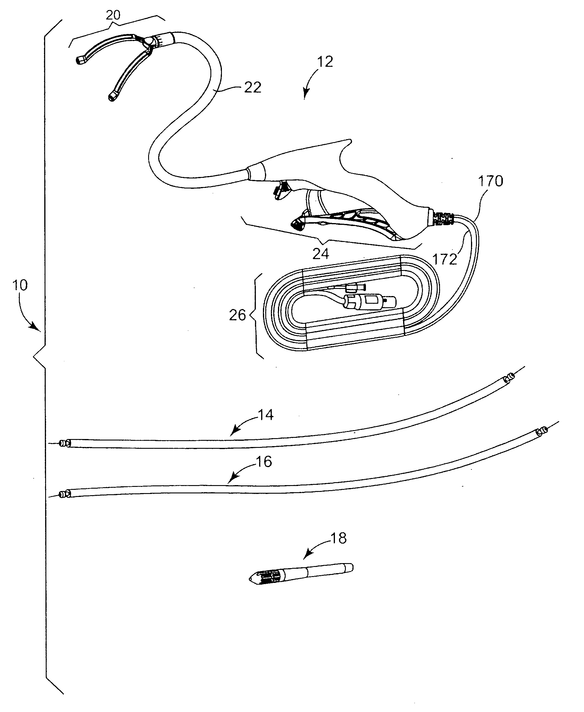
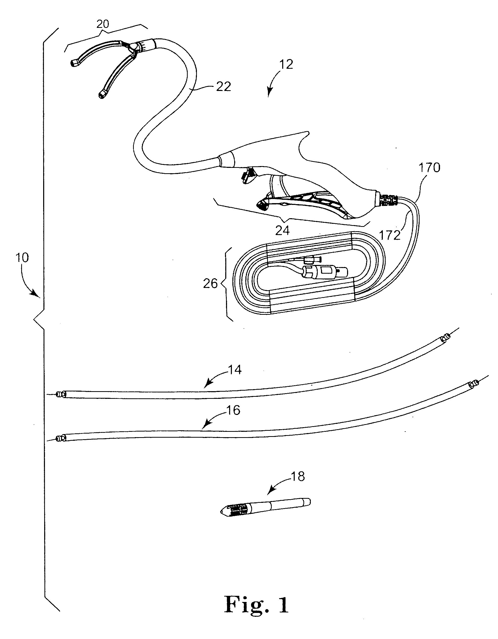
ablation devices include ablating elements connected to rigid elements that are difficult to position within a patient.
Manipulation of such rigid elements is problematic and can lead to
tissue damage.
Such separate controls may cause the surgeon to direct attention away from the patient.
In addition, such separate controls may be out of reach of the surgeon, which means another person may need to manipulate the controls.
These issues relating to the proximity of the controls to the surgeon can result in erroneous application of ablative energy at undesired locations in a patient or at undesired times during an ablation procedure.
Additionally, with regard to some
minimally invasive procedures in particular, such remote controls or switches may be required to be moved around the operating room as the surgeon moves around to access different parts of the body, which is not desired.
Even if controls for activating the ablative
energy source are located on a
handle of the ablation device that is in the hands of the surgeon, during manipulation and placement of the device within a body, the ablative energy controls (e.g., trigger) can be accidentally activated when not desired.

