Subcutaneous lead fixation mechanisms

a subcutaneous lead and fixation mechanism technology, applied in the direction of internal electrodes, transvascular endocardial electrodes, therapy, etc., can solve the problems of inability to remove intracardial fluid, complex current implanted subcutaneous coil leads, time-consuming implanting,

Active Publication Date: 2007-08-30
MEDTRONIC INC
View PDF17 Cites 62 Cited by
  • Summary
  • Abstract
  • Description
  • Claims
  • Application Information

AI Technical Summary

Problems solved by technology

Current implanted subcutaneous coil leads are complicated and time consuming to implant and may dislodge or pull back...

Method used


Image

  • Subcutaneous lead fixation mechanisms
  • Subcutaneous lead fixation mechanisms
  • Subcutaneous lead fixation mechanisms

Examples


Embodiment Construction

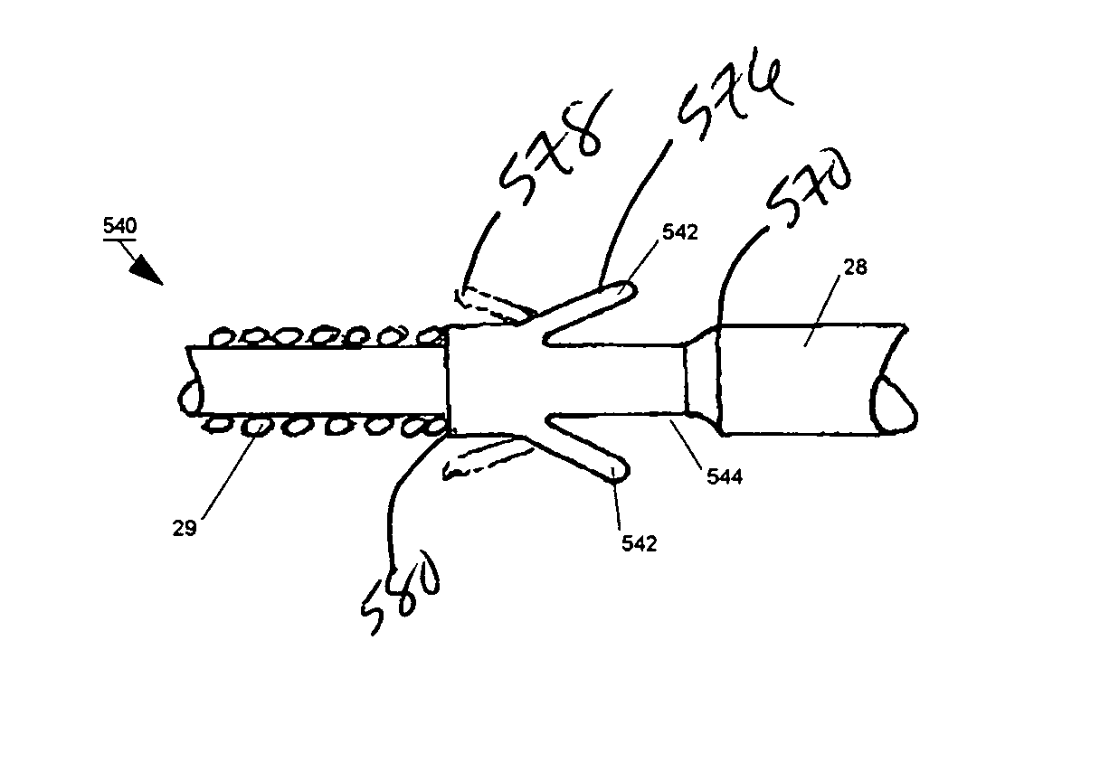
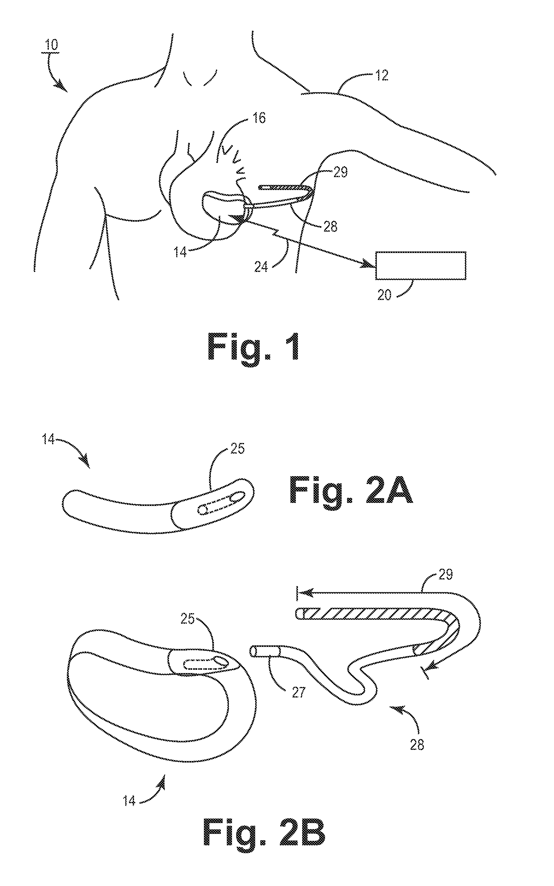
[0019]FIG. 1 is a schematic diagram of a subcutaneous medical device implanted in a patient according to an embodiment of the present invention. As illustrated in FIG. 1, a subcutaneous medical device includes a hermetically sealed housing 14 that is subcutaneously implanted outside a patient's 12 ribcage anterior to the cardiac notch and a subcutaneous sensing and cardioversion / defibrillation therapy delivery lead 28 extending from the housing 14 to be positioned in relation to the heart 16. The cardiac notch is the lateral deflection of the anterior border / boundary of the left lung, which accommodates the space taken up by the heart. Lead 28 is tunneled subcutaneously from the median implant pocket of housing 14 laterally and posterially to the patient's back to a location opposite the heart such that the heart 16 is disposed between the housing 14 and a distal electrode coil 29 of subcutaneous lead 28.

[0020] Further referring to FIG. 1, a programmer 20 may be positioned in telem...


PUM


Abstract

A medical device that includes a lead having a lead body extending from a proximal end to a distal end, and a housing having a connector block for receiving the proximal end of the lead body. A fixation mechanism is positioned proximal to an electrode coil located at the distal end of the lead body, and a fixation member or a plurality of fixation members extend from the fixation mechanism from a fixation member proximal end to a fixation member distal end. The fixation members are advanceable from a first position corresponding to the fixation member distal end being positioned along the lead during subcutaneous placement of the lead, to a second position corresponding to the fixation member distal end being positioned away from the lead to fixedly engage the lead at a target site.

Description

FIELD OF THE INVENTION [0001] The present invention generally relates to an implantable subcutaneous lead for use with an implantable medical device, and more particularly, to a lead that includes deployable fixation means for positively fixating the lead at an implantation site. BACKGROUND OF THE INVENTION [0002] Many types of implantable medical devices (IMDs) have been clinically implanted over the last twenty years that deliver relatively high-energy cardioversion and / or defibrillation shocks to a patient's heart when a malignant tachyarrhythmia, e.g., atrial or ventricular fibrillation, is detected. Cardioversion shocks are typically delivered in synchrony with a detected R-wave when fibrillation detection criteria are met, whereas defibrillation shocks are typically delivered when fibrillation criteria are met and an R-wave cannot be discerned from the EGM. [0003] Current implantable cardioverter / defibrillators (ICDs) or implantable pacemaker / cardioverter / defibrillators (PCDs)...

Claims


Application Information

Patent Timeline
IPC IPC(8): A61N1/05
CPCA61N1/05A61N1/3968A61N1/057A61N1/0504
Inventor RUTTEN, JEAN J. G.KRETZERS, LEONARDUS J. C.SMITS, KAREL FAA
Owner MEDTRONIC INC
Why Eureka
Try Eureka