Means and method for fireproof sealing between the peripheral edge of individual floors of a building and the exterior wall structure thereof

a technology for individual floors and exterior walls, applied in the direction of walls, buildings, building roofs, etc., can solve the problems of severely compromising the fireproofing characteristics surrounding the particular floor, and compromising the positioning of spandrel insulation, so as to prevent the outer deflection of the safing stiffening means and prevent the overheating of the safing stiffening

Inactive Publication Date: 2007-09-06
SPECIFIED TECH
View PDF26 Cites 44 Cited by
  • Summary
  • Abstract
  • Description
  • Claims
  • Application Information

AI Technical Summary

Benefits of technology

[0023] It is an object of the present invention to provide a means and method for fireproof sealing between the peripheral edges of individual floors of a building and the exterior wall structure thereof, wherein the perimeter zone of the floor is sealed with an approved material that extends the rating of the exterior wall surface which prevents overheating of the safing stiffening means.
[0

Problems solved by technology

If the insulation support member becomes overheated, it may tend to bend or warp which could severely compromise the positioning of the safing insulation, or it could also possibly compromise the positioning of

Method used


Image

  • Means and method for fireproof sealing between the peripheral edge of individual floors of a building and the exterior wall structure thereof
  • Means and method for fireproof sealing between the peripheral edge of individual floors of a building and the exterior wall structure thereof
  • Means and method for fireproof sealing between the peripheral edge of individual floors of a building and the exterior wall structure thereof

Examples


Embodiment Construction

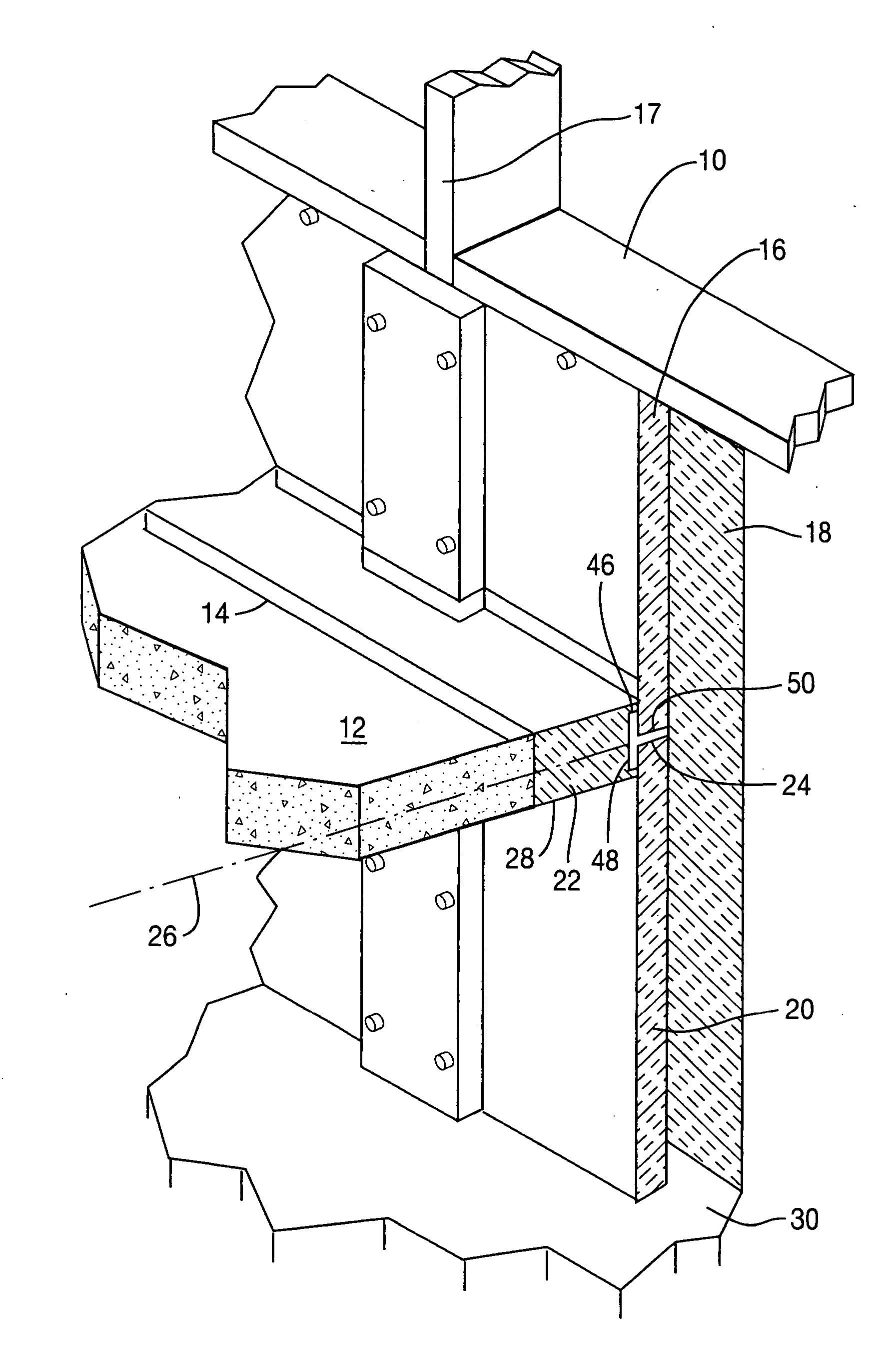
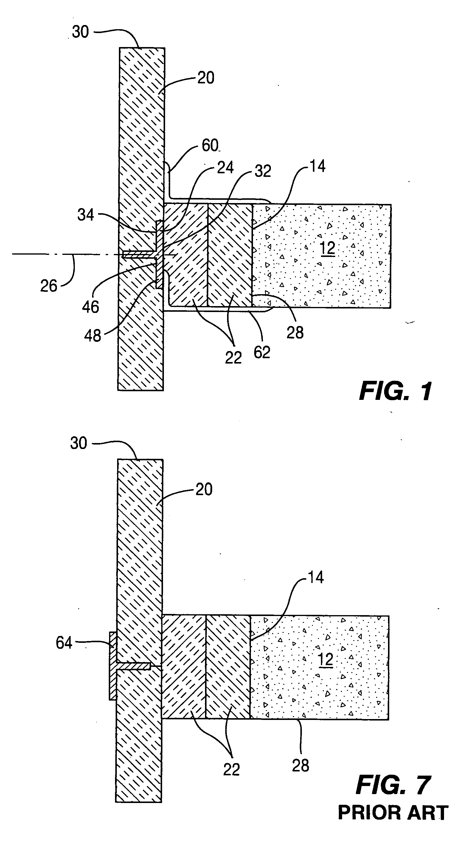
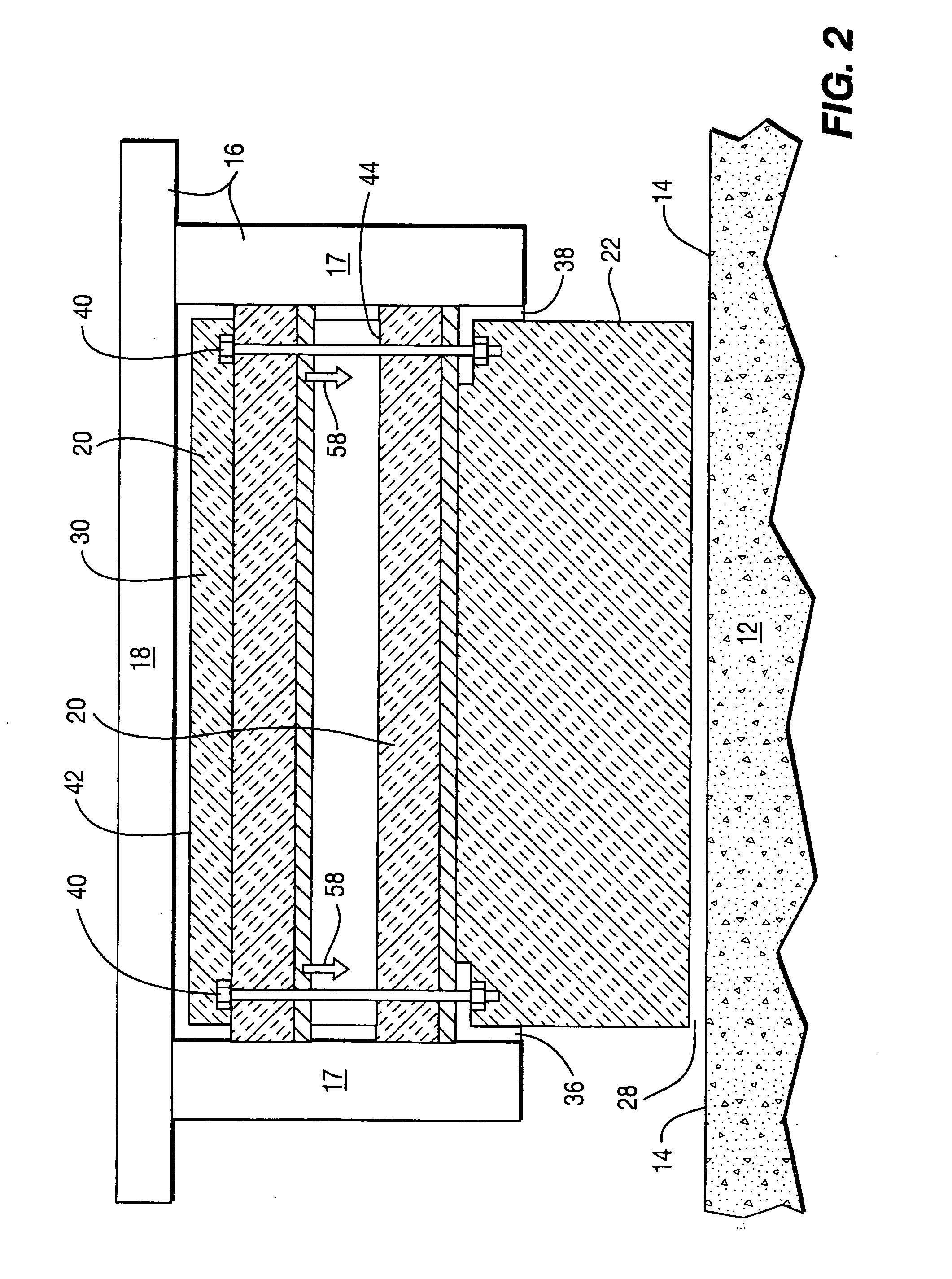
[0033] The present invention provides an improved means and method for providing a fireproofing seal within a building 10 about the individual floors 12 thereof, and particularly, about the outer peripheral edges 14 of these floors 12. A seal fireproofing seal needs to be provided between the exterior wall structure 16 and the peripheral edges 14 of the floor 12 in order to prevent the movement of hot gases, fire, smoke and heat upwardly therethrough in order to prevent fire from spreading upwardly within a building by maintaining compartmentalization of the building and of the fire located within a particular floor therein. The exterior wall structure 16 of the conventional building includes vertically extending wall members 17 which can comprise studs of wood or metal often in commercial buildings formed of aluminum. These vertical wall members 17 are spaced apart from one another, and spandrel panels 18 are secured extending thereover normally used as a portion of the exterior cl...


PUM


Abstract

A construction and a method for fireproof sealing between the outer edges of a floor and the exterior wall structure of a building which includes the placement of an insulation support member between the safing insulation positioned immediately around the floor edge, and the spandrel insulation extending between the vertical studs inside of the outer cladding. Safing insulation is normally compressed prior to placement, and this compression is maintained by positioning the insulation support member in abutment therewith. Also, by positioning the insulation support member between the safing insulation and the spandrel insulation, the support member itself is protected which enhances maintenance of the effective seal of the slot between the floor and the outer cladding. Also during installation, the insulation support member can be used to achieve a desired compression of the safing insulation by positioning it after initial positioning of the insulation member such that it is compressed during final installation of the insulation member.

Description

BACKGROUND OF THE INVENTION [0001] 1. Field Of The Invention [0002] The present invention deals with a field of devices for providing a means of sealing the perimeter joint or slot defined between a normally conventional concrete floor, and the exterior wall construction of a building. It is necessary to make a seal in this slot for the purposes of minimizing the flow of smoke, fire or heat from one floor upwardly to the floor immediately thereabove. Such seal, often defined as a smoke seal, is designed to seal the flow of any hot gases also. Each floor is deemed to be a separate zone, and it is desirable that all fire, smoke, heat and hot gases be contained or compartmentalized within each area to prevent spreading to an adjacent area to minimize spreading of the fire. In this manner, a maximum amount of time is given for individuals to exit the building after a fire starts, and also it maximizes the chance for fire personnel to treat the fire prior to spreading thereof to multiple...

Claims


Application Information

Patent Timeline
IPC IPC(8): E04B1/00
CPCE04B5/00E04B1/94E04B2/88
Inventor STAHL, JAMES P. SR.STAHL, JAMES P. JR.
Owner SPECIFIED TECH
Why Eureka
Try Eureka