Engine starting device

a technology of engine starting and starting gear, which is applied in the direction of engine starting, machine/engine, electric control, etc., can solve the problems of large driving torque degrading the engine response, the rotational speed cannot increase easily, and the engine is not easy to accelerate, so as to improve the starting speed and accelerate the engine. the effect of the engine, preventing the acceleration performance of the engine from dropping, and excessive performan

Inactive Publication Date: 2007-09-06
KOKUSAN DENKI CO LTD
View PDF11 Cites 55 Cited by
  • Summary
  • Abstract
  • Description
  • Claims
  • Application Information

AI Technical Summary

Benefits of technology

[0037]As described above, according to the present invention, by providing the starter forward rotational drive means, which continues driving a starter motor in a direction for starting an engine until start of an engine is verified, even when a crankshaft stops before a piston in a cylinder reaches a top dead center of a compression stroke in starting the engine, it is made to make an engine complete a compression stroke by using gradual decrease of a compression torque by engine compression leakage when a crankshaft stops or is in a state just before a stop before the piston in the cylinder reaches the top dead center of the compression stroke because a maximum load torque applied to the crankshaft of the engine is excessive in relation to an output torque of the starter motor, and therefore, even when the load torque applied to the crankshaft of the engine is excessive in relation to the output torque of the starter motor, it is possible to start the engine without a hitch.
[0038]Therefore, according to the present invention, it is possible to enhance a startability of the engine without causing increase of cost or causing upsizing of a device by using a starter motor which has excessive performance. In addition, because it is possible to us

Problems solved by technology

When the crankshaft is forwardly rotated so as to start the engine from this position, a compression load in a compression stroke is applied to the crankshaft immediately after the rotation is started, and therefore, the rotational speed does not increase easily and the largest load is applied to a starter motor at a crank angle position where the compression load becomes maximum.
In particular, when a rotor of a starter motor is directly connected to a crankshaft, such as the case where a generator whose rotor is directly connected to the crankshaft is used as a starter motor in starting the engine, there is a problem that a large and expensive motor must be used because the motor torque cannot be increased by a reduction gear.
In addition, when a starter motor is used as a generator after the engine is started, using a motor having a large driving torque degrades the engine response because of the large mass of the rotor that causes an excessive inertia.
Because the startability and response of an engine are in an antinomical relation, it had not been ea

Method used


Image

  • Engine starting device
  • Engine starting device
  • Engine starting device

Examples


Embodiment Construction

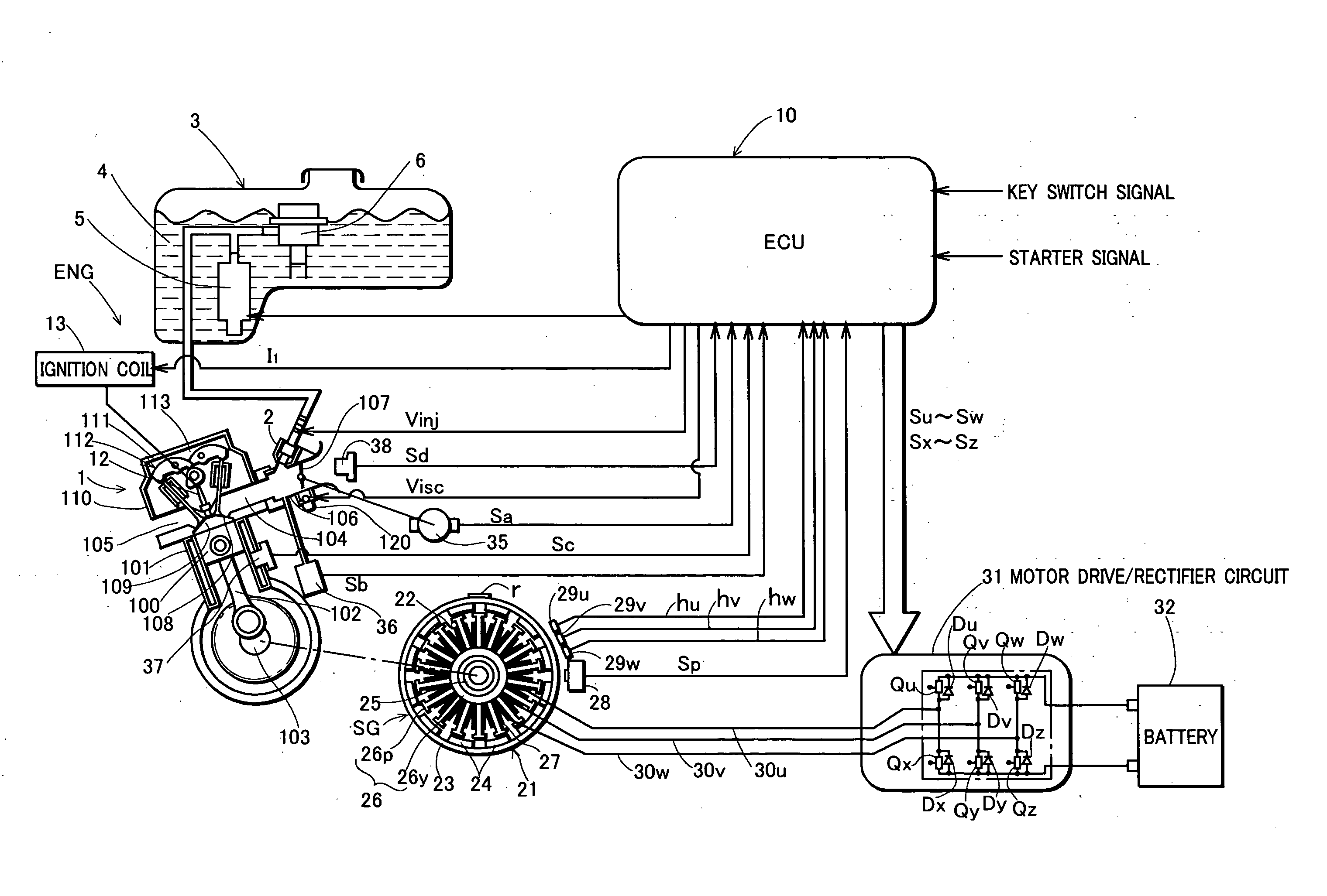
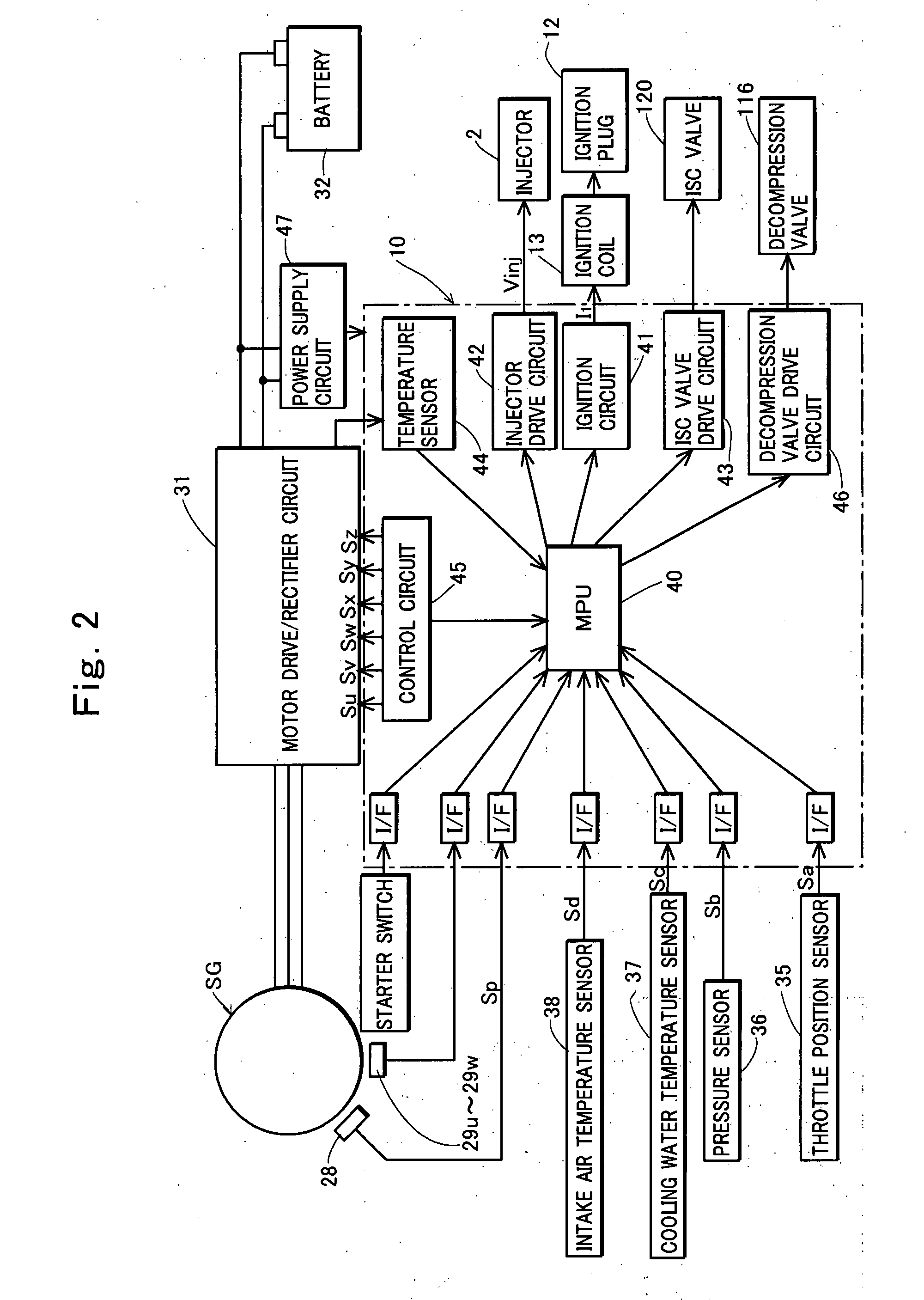
[0059]Before proposing an engine starting device according to the present invention, inventors of the present invention performed a test for searching a reason why it become impossible to start an engine under a very low temperature environment of lower than −20° C. when starting the engine by conventional art by using a small starter motor whose output torque was smaller than a maximum load torque (a compression torque) applied to a crankshaft in a compression stroke of the engine, and so its test result will be described before describing preferred embodiments of the present invention.

[0060]In the test which the present inventors performed, a parallel two-cylinder four-cycle engine whose engine displacement is 700 cc was taken for example. In this engine, a phase shift between a first cylinder (abbreviated as #1 in the drawing) and a second cylinder (abbreviated as #2 in the drawing) is 360° in a crank angle, and correspondence between strokes of the first cylinder and the second ...


PUM


Abstract

An engine starting device which makes fuel injected in preparation for ignition performed in a cylinder of an engine after starting drive of a starter motor in a forward rotational direction so as to start the engine, and makes ignition performed in a suitable ignition position at the time of engine start while the starter motor is driven in a forward rotational direction, the engine starting device being comprised so as to continue driving the starter motor in a direction for starting the engine, even when a crankshaft stops before a piston in a cylinder of the engine reaches a top dead center of a compression stroke.

Description

TECHNICAL FIELD OF THE INVENTION[0001]The present invention relates to an engine starting device which starts an engine comprising a starter motor.BACKGROUND OF THE INVENTION[0002]Usually, when an engine is stopped, a compression load in a compression stroke of the engine serves as a brake, while a crankshaft is rotating through inertia, so that the rotation momentarily stops in the course of a piston in any of cylinders rising toward a top dead center of the compression stroke, and thereafter, the piston is often pushed back and stopped near a bottom dead center. Therefore, when the engine is started, a crankshaft will be rotated with a piston in any of cylinders located near a bottom dead center of a compression stroke.[0003]When the crankshaft is forwardly rotated so as to start the engine from this position, a compression load in a compression stroke is applied to the crankshaft immediately after the rotation is started, and therefore, the rotational speed does not increase easi...

Claims


Application Information

Patent Timeline
IPC IPC(8): F02N17/00F02M1/00F02N99/00
CPCF02N11/08F02N19/005F02P15/08F02N2019/007F02N99/006
Inventor KISHIBATA, KAZUYOSHISHIMAZAKI, MITSUYOSHIKINOSHITA, TOMOHIRO
Owner KOKUSAN DENKI CO LTD
Why Eureka
Try Eureka