
Molded composite climbing structures utilizing selective localized reinforcement

a composite and localized reinforcement technology, applied in the field of climbing structures, can solve the problems of structural failure, debilitating deterioration, gradual loosening of steps and braces, and gradual loosening of steps and braces, and achieve the effect of increasing the amount of composite material fibers and less structural stress

Inactive Publication Date: 2007-09-06
CMX TECH
View PDF32 Cites 31 Cited by
  • Summary
  • Abstract
  • Description
  • Claims
  • Application Information

AI Technical Summary

Benefits of technology

[0012] In light of the problems and deficiencies inherent in the prior art, the present invention seeks to overcome these by providing a method and system for fabricating molded composite support members for use in climbing structures, which molded composite support members comprise variable performance properties along a longitudinal length thereof. The variable performance properties are achieved or provided by selectively reinforcing one or more regions determined to be subject to greater stress, thus allowing a minimum amount of material to be used in other areas that will subject to less structural stress. Selective reinforcement is accomplished by adapting one or more regions of a primary composite material composition with a supplemental composite material composition, wherein the supplemental composite material composition increases the amount of composite material fibers within that particular region.
[0013] In accordance with the invention as embodied and broadly described herein, the present invention resides in a climbing structure configured to support a load, the climbing structure comprising a surface operable to receive a load thereon; and at least one composite support member configured to support the surface, and having variable performance properties along a longitudinal length thereof, the composite support member comprising a primary composite material composition having an elongate, channel-shaped configuration; and a supplemental composite material composition operable to adapt selective regions of the primary composite material composition to provide selective localized reinforcement for facilitating and enhancing the variable performance properties.
[0014] The present invention also resides in a composite support member operable within a climbing structure, the composite support member comprising a primary composite material composition having an elongate, channel-shaped configuration, and comprising material fibers oriented on a zero degree angle with respect to a longitudinal axis of the support member; and a supplemental composite material composition operable to selectively reinforce the primary composite material composition and to facilitate variable performance properties of the support member along a longitudinal length thereof, the supplemental composite material composition comprising a plurality of composite material fibers oriented to enhance the performance properties.
[0015] The present invention also resides in a composite support member for use within a climbing structure, the composite support member comprising a primary composite material composition having an elongate, channel-shaped configuration; and a supplemental composite material composition operable to adapt the primary composite material composition along substantially an entire length thereof, to provide reinforcement for facilitating and enhancing one or more performance properties of the primary composite material composition, the primary composite material composition and the supplemental composite material composition configured to provide a uniform cross-sectional area along a longitudinal length of the support member.
[0016] The present invention further resides in a method for fabricating a composite support member operable within a climbing structure, the method comprising preparing a primary composite material composition having an elongate, channel-shaped configuration; preparing a supplemental composite material composition; adapting a region of the primary composite material composition with the supplemental composite material composition to provide selective localized reinforcement of the primary composite material composition, and to form the composite support member, the supplemental composite material facilitating variable performance properties along a longitudinal length of the support member.

Problems solved by technology

Solid (i.e. non-laminated) pieces of wood used in the construction of ladders may have latent defects which can cause a structural failure.
Wood is also subject to gradual, debilitating deterioration by moisture, sun, insects and microorganisms.
Furthermore, expansion and contraction of wood caused by temperature and humidity changes can result in a gradual loosening of steps and braces, which requires frequent maintenance.
Wood ladders also tend to be less stable in larger sizes.
Though aluminum alloys offer a high strength, lightweight alternative to wood, ladders made of aluminum alloys also have a number of drawbacks.
Certain chemicals and salt water environments can corrode and weaken aluminum ladders.
Although having excellent uniformity in the strength of structural members at the time of manufacture, the rails of aluminum ladders are easily bent and cracked.
The most significant drawback is that aluminum is the third-best conducting metal.
This attribute makes aluminum ladders extremely dangerous for work anywhere near high-voltage electrical wires.
Unfortunately, a ladder coming into contact with an electrical wire often occurs by accident.
Therefore, a risk of electrocution may exist even when care is taken to avoid known and visible hazards.
The problem is compounded because the light weight and high strength characteristics of metal ladders may be an inducement for their use even when electrical safety is a concern.
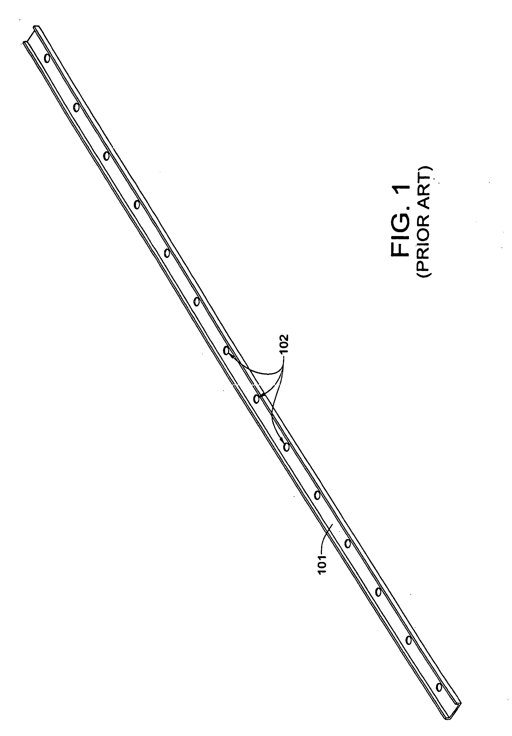
The greatest weakness of the composite pultrusion and aluminum extrusion manufacturing processes is that the cross-sectional profile of the rail must remain constant throughout its entire length.
Thus, a ladder rail of uniform cross section throughout its length is necessarily overly strong and heavy throughout much of its length, while those regions subjected to maximum stress, torque, shear, flex and abuse are designed to be just strong enough to support the maximum rated load—plus an additional safety factor load—without failure, under expected usage conditions.
Neither the extrusion process nor the pultrusion process is readily adaptable to the manufacture of rails of non-uniform cross section over their lengths.
The purchase price is likely only a tiny fraction of the total costs related to treating and compensating potentially career-ending physical injuries sustained while carrying, loading, unloading, setting up, and taking down a conventional ladder over its useful life.
As a result, providing localized reinforcement in needed areas or regions only in order to minimize material in other areas or regions, thus saving weight and costs, has also largely been ignored by manufacturers of these types of climbing structures.

Method used


Image

  • Molded composite climbing structures utilizing selective localized reinforcement
  • Molded composite climbing structures utilizing selective localized reinforcement
  • Molded composite climbing structures utilizing selective localized reinforcement

Examples


first embodiment

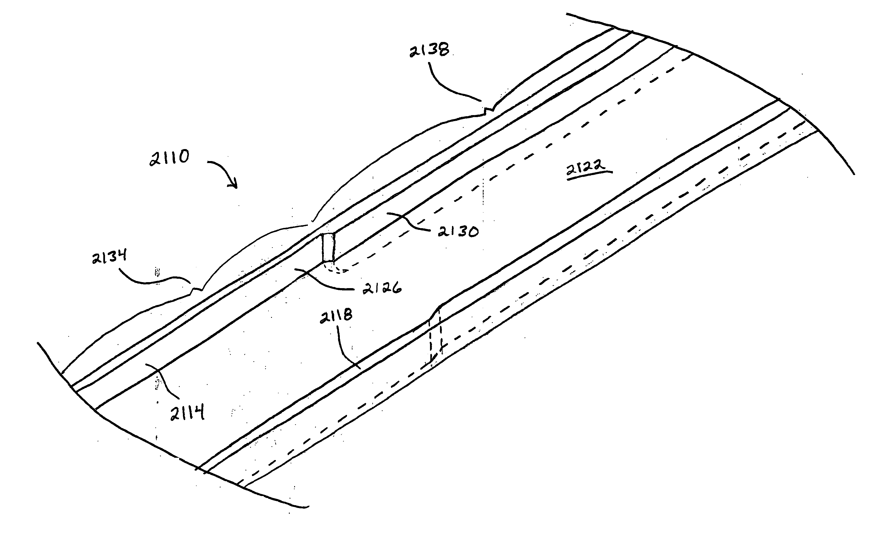
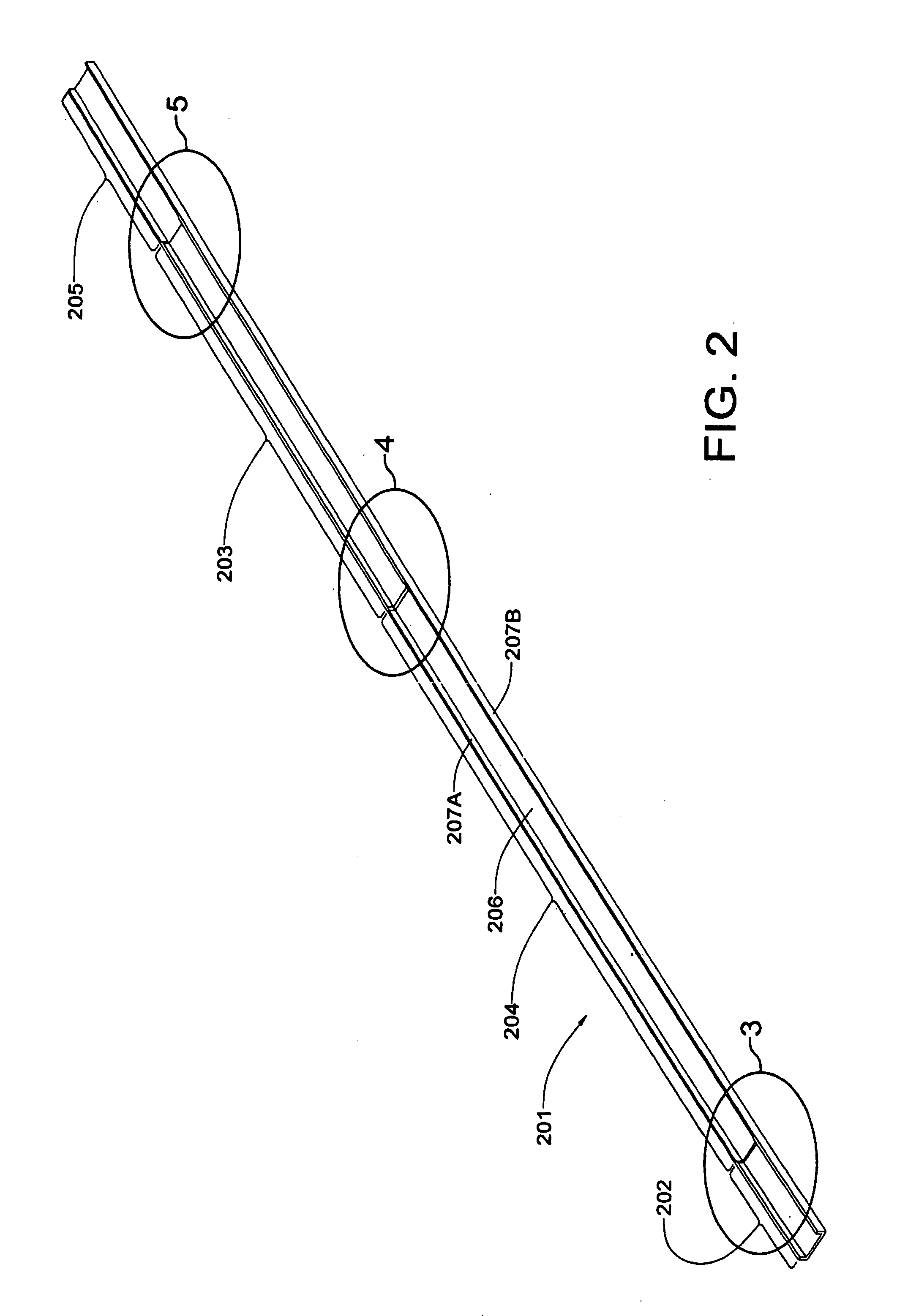
[0078] Referring now to FIG. 2, a first embodiment composite ladder rail 201 is shown that may be used in the fabrication of a base section of a non-self-supporting extension ladder such as the one that is the subject of U.S. Pat. No. 5,758,745 (the '745 patent) granted to Robert D. Beggs, et al. This patent is hereby incorporated by reference into the present application. The rail 201 has a flattened C-shaped cross-section, which is of non-uniform area throughout its length. The rail 201 comprises a rail back 206 and rail flanges 207A and 207B extending upward from the rail back 206. The rail 201 has an augmented cross-sectional area at the lower end 202, to which a hingeable foot will be attached in a conventional manner, and at a maximum and near-maximum extension overlap region 203. As the foot of the ladder is subject to impact abuse, it would benefit from being reinforced with additional structural fibers for added strength. The overlap region 203 would also benefit from being...

second embodiment

[0082] Referring now to FIG. 6, a second embodiment composite ladder rail 601 is shown that may be used in the fabrication of a self-supporting combination step and extension ladder such as the one that is the subject of U.S. Pat. No. 4,371,055 (the '055 patent) granted to Larry J. Ashton, et al. This patent is hereby incorporated by reference into the present application. The ladder of the '055 patent includes a pair of base sections, each of which is fabricated from a plurality of rungs interconnecting a pair of channeled outer side rails of molded fiberglass, and a pair of fly sections, each of which is fabricated from a plurality of rungs interconnecting a pair of inner side rails of molded of fiberglass. Each of the inner side rails is telescopically mounted within an outer side rail so that the inner side rails can be extended to increase the height of the ladder in either configuration. The two fly sections are hinged together at the top ends so that the ladder may be folded ...


PUM

PropertyMeasurementUnit
zero degree angleaaaaaaaaaa
angleaaaaaaaaaa
angleaaaaaaaaaa

Abstract

A method and system for fabricating molded composite support members for use in climbing structures, which molded composite support members comprise variable performance properties along a longitudinal length thereof. The variable performance properties are achieved or provided by selectively reinforcing one or more regions determined to be subject to greater stress, thus allowing a minimum amount of material to be used in other areas that will subject to less structural stress. Selective reinforcement is accomplished by adapting one or more regions of a primary composite material composition with a supplemental composite material composition, wherein the supplemental composite material composition increases the amount of composite material fibers within that particular region.

Description

RELATED APPLICATIONS [0001] This continuation in-part application claims the benefit of U.S. application Ser. No. 10 / 919,420, filed Aug. 16, 2004, and entitled, “Lightweight Composite Ladder Rail Having Supplemental Reinforcement in Regions Subject to Greater Structural Stress,” which is incorporated by reference in its entirety herein.FIELD OF THE INVENTION [0002] This invention relates to various types of climbing structures, as well as to the support members used in the manufacture and / or assembly of such climbing structures, and more particularly to molded composite support members for use in climbing structures. BACKGROUND OF THE INVENTION AND RELATED ART [0003] Climbing structures, such as ladders, scaffolding, platforms, bleachers and others, in which a load (e.g., an individual or individuals, an object or objects, equipment, etc.) is intended to be supported are extremely common, and have found useful application in several different commercial settings and industries, in r...

Claims


Application Information

Patent Timeline
Patent Type & Authority Applications(United States)
IPC IPC(8): E06C5/04
CPCB29C43/003B29C70/202B29C70/443B29C2043/3644E06C7/08B29K2105/0854B29L2031/06B29L2031/745B29K2105/0029
Inventor ISHAM, WILLIAM R.WEBBER, STEPHEN N.
Owner CMX TECH
Learn More